Installation [11/2023 - ]: Procedure
- INSTALL LOWER NO. 1 INSTRUMENT PANEL AIRBAG ASSEMBLY
- Check that the ignition switch is off.
- Check that the cable is disconnected from the negative (-) auxiliary battery terminal.WARNING:
Wait at least 60 seconds after disconnecting the cable from the negative (-) auxiliary battery terminal to disable the SRS system.
- Connect the airbag connector to the lower No. 1 instrument panel airbag assembly.NOTE:
When connecting any airbag connector, take care not to damage the airbag wire harness.
HINT:
Refer to How to Connect or Disconnect Airbag Connector.
Refer to HOW TO CONNECT OR DISCONNECT AIRBAG CONNECTOR [11/2023 - ]
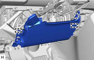
- Engage the 2 hooks to temporarily install the lower No. 1 instrument panel airbag assembly.
- Engage the claw.
- Install the lower No. 1 instrument panel airbag assembly with the 4 bolts.
Torque: 10 N*m (102 kgf*cm, 7 ft.*lbf)
NOTE:Confirm that the lower No. 1 instrument panel airbag assembly is installed securely without any excessive gaps and is not protruding outward.
- INSTALL NO. 1 SWITCH HOLE BASE
Refer to PROCEDURE - Step 25
- INSTALL LOWER INSTRUMENT PANEL FINISH PANEL SUB-ASSEMBLY
Refer to PROCEDURE - Step 26
- INSTALL HOOD LOCK CONTROL LEVER SUB-ASSEMBLY
Refer to PROCEDURE - Step 27
- INSTALL NO. 1 INSTRUMENT PANEL UNDER COVER SUB-ASSEMBLY
Refer to PROCEDURE - Step 28
- INSTALL COWL SIDE TRIM SUB-ASSEMBLY LH
Refer to PROCEDURE - Step 49
- INSTALL FRONT DOOR SCUFF PLATE LH
Refer to PROCEDURE - Step 50
- CONNECT CABLE TO NEGATIVE AUXILIARY BATTERY TERMINAL
for T24A-FTS: Refer to PROCEDURE - Step 4
for A25A-FXS: Refer to PROCEDURE - Step 2
- INSTALL BATTERY SERVICE HOLE COVER (for HV Model)
Refer to PROCEDURE - Step 3
- INSPECT SRS WARNING LIGHT
Refer to OPERATION CHECK [11/2023 - ]
- INITIALIZATION AFTER RECONNECTING AUXILIARY BATTERY TERMINAL
HINT:
When disconnecting and reconnecting the auxiliary battery, there is an automatic learning function that completes learning when the respective system is used.