Installation [12/2019 - 10/2022]: Procedure
- INSTALL TRANSMISSION WIRE
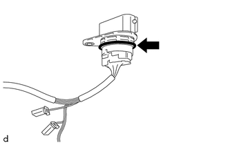
- Coat the O-ring of the transmission wire with Toyota Genuine ATF WS.
- Install the transmission wire to the automatic transaxle case sub-assembly with the bolt.
Torque: 5.4 N.m (55 kgf/cm, 48 in.lbf)
- Connect the transmission revolution sensor (NT) connector and transmission revolution sensor (NC) connector.
- Install the temperature sensor to the transmission valve body assembly with the bolt and temperature sensor clamp.
Torque: 10.8 N.m (110 kgf/cm, 8 ft.lbf)
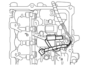
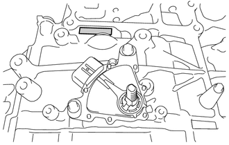
NOTE:To prevent it from being pinched between the transmission valve body assembly and the transmission case side cover, pass the transmission revolution sensor (NC) wire under the transmission wire (temperature sensor wire) as shown in the illustration.
*a Transmission Wire (Temperature Sensor Wire) *b Transmission Revolution Sensor (NC) Wire - Engage the clamp to connect the transmission wire (oil pump with solenoid assembly) to the solenoid lock plate.
- Connect the transmission wire connector.
- Engage the wire harness clamp to connect the transmission wire (oil pump with solenoid assembly).
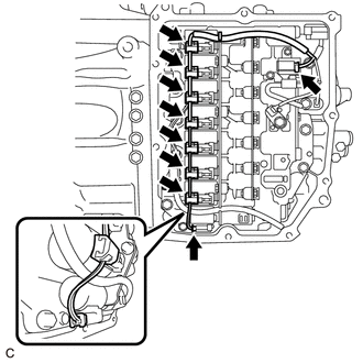
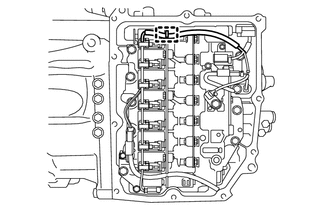
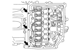
- Connect the 9 solenoid valve connectors as shown in the illustration.NOTE:

Do not let transmission wire protrude into this area. - To prevent it from being pinched between the transmission valve body assembly and the transmission case side cover, do not let the transmission wire ride up over the area shown in the illustration.
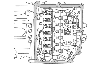
- To prevent it from being pinched between the transmission case side cover and the automatic transaxle case sub-assembly, do not let the transmission wire protrude toward the transmission case side cover installation surface.
- Engage the clamp, and connect the transmission wire to the solenoid lock plate.
- Coat the O-ring of the transmission wire with Toyota Genuine ATF WS.
- INSTALL TRANSMISSION CASE SIDE COVER (for AW (AISIN AW) Made)
HINT:
Serial Number The component manufacturer (AW (AISIN AW) or TMMWV (TOYOTA)) can be determined based on the serial number as described in the following table.
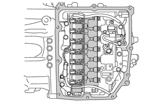
Serial Number Factory ##6######## AW (AISIN AW) ##A######## TMMWV (TOYOTA) - Clean the transmission case side cover installation surface of the automatic transaxle case sub-assembly.
Area to be cleaned NOTE:Completely remove any oil or grease from the contact surfaces of the automatic transaxle case sub-assembly.
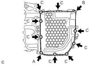
- Temporarily install a new transmission case side cover to the automatic transaxle case sub-assembly with the 2 bolts ((A) and (B)).NOTE:
To avoid damaging the gasket, prevent it from contacting the surrounding area during installation procedures.
- Temporarily install the 8 bolts (C).
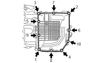
- Fully tighten the 10 bolts in the order shown in the illustration.
 Courtesy of © TOYOTA, LICENSE AGREEMENT TMS1002
Torque: 7.0 N.m (71 kgf/cm, 62 in.lbf)
- Clean the transmission case side cover installation surface of the automatic transaxle case sub-assembly.
- INSTALL TRANSMISSION CASE SIDE COVER (for TMMWV Made)
HINT:
Serial Number The component manufacturer (AW (AISIN AW) or TMMWV (TOYOTA)) can be determined based on the serial number as described in the following table.
Serial Number Factory ##6######## AW (AISIN AW) ##A######## TMMWV (TOYOTA) - Clean the transmission case side cover installation surface of the automatic transaxle case sub-assembly.
Area to be cleaned NOTE:Completely remove any oil or grease from the contact surfaces of the automatic transaxle case sub-assembly.
- Clean the 3 bolt holes shown in the illustration.
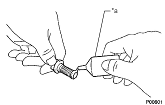
- Apply adhesive to 2 or 3 threads on the end of the bolt (A) and 2 bolts (D).
Adhesive
Toyota Genuine Adhesive 1324, Three Bond 1324 or equivalent
NOTE:Make sure to install the bolts immediately after applying adhesive to prevent foreign matter from attaching to them.
*a Adhesive HINT:
The bolt (A) and 2 bolts (D) are in the locations shown in the following step.
- Temporarily install a new transmission case side cover to the automatic transaxle case sub-assembly with the 2 bolts ((A) and (B)).NOTE:
- Bolt (A) is the adhesive-coated bolt.
- To avoid damaging the gasket, prevent it from contacting the surrounding area during installation procedures.
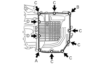
- Temporarily install the 6 bolts (C) and 2 bolts (D).NOTE:
Bolts (D) are the adhesive-coated bolts.
- Fully tighten the 10 bolts in the order shown in the illustration.
 Courtesy of © TOYOTA, LICENSE AGREEMENT TMS1002
Bolt (A) and Bolt (D)
Torque: 6.5 N.m (66 kgf/cm, 58 in.lbf)
Bolt (B) and Bolt (C)
Torque: 7.0 N.m (71 kgf/cm, 62 in.lbf)
- Clean the transmission case side cover installation surface of the automatic transaxle case sub-assembly.
- INSTALL OIL COOLER UNION SUB-ASSEMBLY
- Pass the oil cooler union sub-assembly through 2 new gaskets and temporarily install it to the automatic transaxle case sub-assembly with the oil cooler union bolt.
*1 Oil Cooler Union Bolt *2 Gasket - Temporarily install the oil cooler union sub-assembly bracket portion to the automatic transaxle case sub-assembly with the bolt.
- Fully tighten the oil cooler union bolt.
Torque: 22.6 N.m (230 kgf/cm, 17 ft.lbf)
- Fully tighten the bolt.
Torque: 12 N.m (122 kgf/cm, 9 ft.lbf)
- Pass the oil cooler union sub-assembly through 2 new gaskets and temporarily install it to the automatic transaxle case sub-assembly with the oil cooler union bolt.
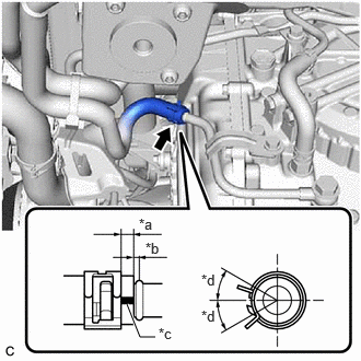
- CONNECT OUTLET NO. 1 OIL COOLER HOSE
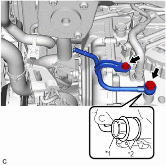
- Connect the outlet No. 1 oil cooler hose to the oil cooler union sub-assembly and slide the clip to secure it.
*a 2 to 7 mm (0.0787 to 0.276 in.) *b 0 to 3 mm (0 to 0.118 in.) *c Paint Mark (Left Side of Vehicle) *d 30° (Paint Mark Location) NOTE:- Make sure to slide the outlet No. 1 oil cooler hose until it contacts the hose stopper of the oil cooler union sub-assembly.
- Make sure that the paint mark of the outlet No. 1 oil cooler hose is within the location shown in the illustration.
- Connect the outlet No. 1 oil cooler hose to the oil cooler union sub-assembly and slide the clip to secure it.
- ADJUST AUTOMATIC TRANSAXLE FLUID
Refer to ADJUSTMENT [12/2019 - 10/2022]
- INSTALL FRONT FENDER APRON SEAL LH
Refer to PROCEDURE - Step 74 [12/2019 - 09/2020] , or refer to PROCEDURE - Step 74 [09/2020 - 10/2022]
- INSTALL FRONT ENGINE MOUNTING INSULATOR
Refer to INSTALLATION [12/2019 - 10/2022]