Installation [09/2020 - 10/2022]: Procedure
- INSTALL NO. 1 OIL COOLER TUBE SUB-ASSEMBLY WITHOUT HOSE
HINT:
Perform this procedure only when replacement of the No. 1 oil cooler tube sub-assembly without hose is necessary.
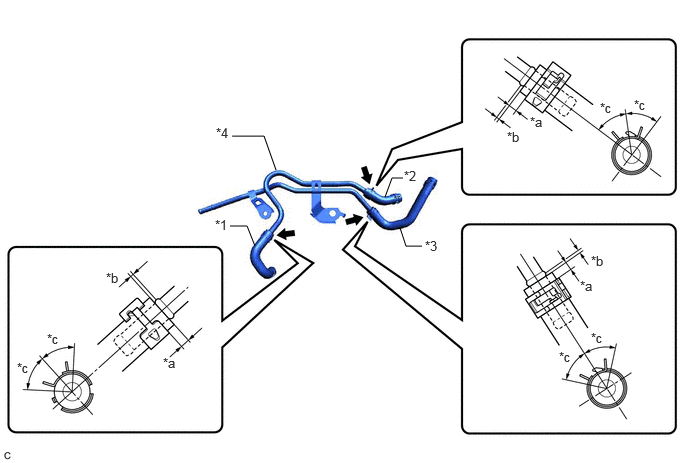
- Install the inlet No. 1 oil cooler hose, inlet No. 2 oil cooler hose and outlet No. 3 oil cooler hose to the No. 1 oil cooler tube sub-assembly without hose and slide the 3 clips to secure them.
*1 Inlet No. 1 Oil Cooler Hose *2 Inlet No. 2 Oil Cooler Hose *3 Outlet No. 3 Oil Cooler Hose *4 No. 1 Oil Cooler Tube Sub-assembly without Hose *a 2 to 7 mm (0.0787 to 0.276 in.) *b 0 to 3 mm (0 to 0.118 in.) *c 45° (Claw of Clip Location) - - NOTE:- Make sure to slide the inlet No. 1 oil cooler hose, inlet No. 2 oil cooler hose and outlet No. 3 oil cooler hose until each contacts the hose stopper of the No. 1 oil cooler tube sub-assembly without hose.
- Make sure that the claws of each clip are within the location shown in the illustration.
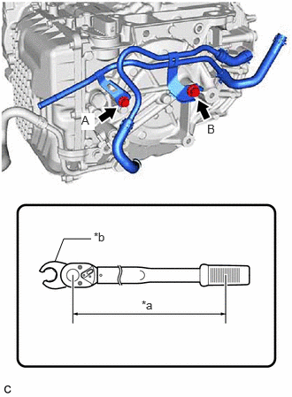
- Temporarily install the No. 1 oil cooler tube sub-assembly without hose to the automatic transaxle case sub-assembly with the 2 bolts.
*a Torque Wrench Fulcrum Length *b Union Nut Wrench - Using a 12 mm union nut wrench, fully tighten the bolt (A).
Specified Tightening Torque
Torque: 13.5 N.m (138 kgf/cm, 10 ft.lbf)
HINT:
- Calculate the torque wrench reading when changing the fulcrum length of the torque wrench.
Refer to PRECAUTION [12/2019 - 11/2023]
- When using a 12 mm union nut wrench (fulcrum length of 20 mm (0.787 in.)) + torque wrench (fulcrum length of 162 mm (6.38 in.)):
12 N.m (122 kgf/cm, 9 ft.lbf)
- Calculate the torque wrench reading when changing the fulcrum length of the torque wrench.
- Using a 14 mm union nut wrench, fully tighten the bolt (B).
Specified Tightening Torque
Torque: 28 N.m (286 kgf/cm, 21 ft.lbf)
HINT:
- Calculate the torque wrench reading when changing the fulcrum length of the torque wrench.
Refer to PRECAUTION [12/2019 - 11/2023]
- When using a 14 mm union nut wrench (fulcrum length of 25 mm (0.984 in.)) + torque wrench (fulcrum length of 180 mm (7.09 in.)):
24.6 N.m (251 kgf/cm, 18 ft.lbf)
- Calculate the torque wrench reading when changing the fulcrum length of the torque wrench.
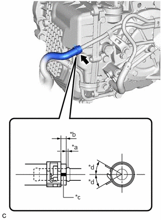
- Connect the inlet No. 1 oil cooler hose to the oil cooler outlet union or elbow and slide the clip to secure it.
*a 0 to 3 mm (0 to 0.118 in.) *b 2 to 7 mm (0.0787 to 0.276 in.) *c End of Paint Mark Visible *d Paint Mark NOTE:- Make sure to slide the inlet No. 1 oil cooler hose until it contacts the hose stopper of the oil cooler outlet union or elbow.
- Make sure that the paint mark of the inlet No. 1 oil cooler hose and clip are within the location shown in the illustration.
- Install the inlet No. 1 oil cooler hose, inlet No. 2 oil cooler hose and outlet No. 3 oil cooler hose to the No. 1 oil cooler tube sub-assembly without hose and slide the 3 clips to secure them.
- CONNECT NO. 3 TRANSMISSION OIL COOLER HOSE
HINT:
Perform this procedure only when replacement of the No. 1 oil cooler tube sub-assembly without hose is necessary.
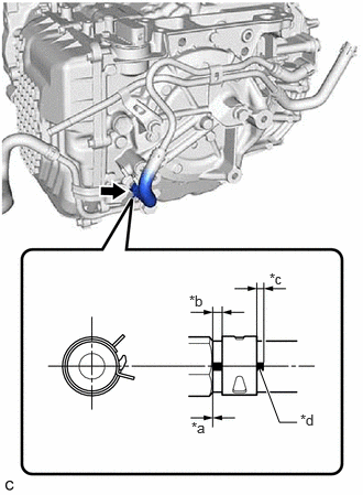
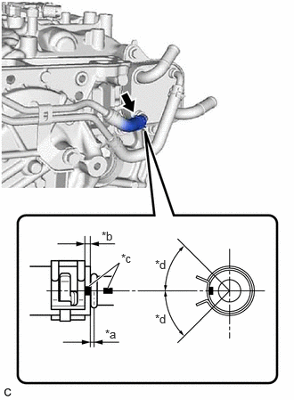
- Connect the No. 3 transmission oil cooler hose to the No. 1 oil cooler tube sub-assembly without hose and slide the clip to secure it.NOTE:
- Make sure to slide the No. 3 transmission oil cooler hose until it contacts the hose stopper of the No. 1 oil cooler tube sub-assembly without hose.
- Make sure that the paint mark of the No. 3 transmission oil cooler hose is within the location shown in the illustration.
- Make sure that the clip is within the location shown in the illustration.
*a 0 to 3 mm (0 to 0.118 in.) *b 2 to 7 mm (0.0787 to 0.276 in.) *c Paint Mark *d 30° (Paint Mark Location)
- Connect the No. 3 transmission oil cooler hose to the No. 1 oil cooler tube sub-assembly without hose and slide the clip to secure it.
- INSTALL TRANSMISSION OIL COOLER
- CONNECT OUTLET NO. 3 OIL COOLER HOSE
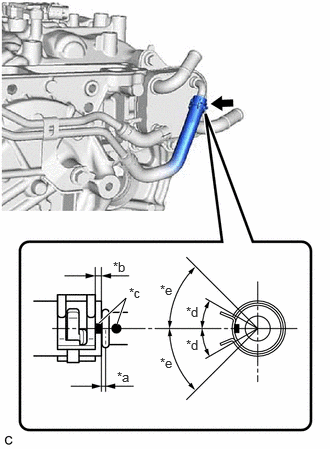
- Connect the outlet No. 3 oil cooler hose to the transmission oil cooler and slide the clip to secure it.
*a 0 to 3 mm (0 to 0.118 in.) *b 2 to 7 mm (0.0787 to 0.276 in.) *c Paint Mark *d 30° (Paint Mark Location) *e 45° (Claw of Clip Location) NOTE:- Make sure to slide the outlet No. 3 oil cooler hose until it contacts the hose stopper of the transmission oil cooler.
- Make sure to align the paint mark of the outlet No. 3 oil cooler hose with paint mark of the transmission oil cooler.
- Make sure that the paint mark of the outlet No. 3 oil cooler hose and claws of the clip are within the location shown in the illustration.
- Connect the outlet No. 3 oil cooler hose to the transmission oil cooler and slide the clip to secure it.
- CONNECT INLET NO. 2 OIL COOLER HOSE
- Connect the inlet No. 2 oil cooler hose to the transmission oil cooler and slide the clip to secure it.NOTE:
- Make sure to slide the inlet No. 2 oil cooler hose until it contacts the hose stopper of the transmission oil cooler.
- Make sure to align the paint mark of the inlet No. 2 oil cooler hose with the paint mark of the transmission oil cooler.
- Make sure that the claws of the clip are within the location shown in the illustration.
*a 0 to 3 mm (0 to 0.118 in.) *b 2 to 7 mm (0.0787 to 0.276 in.) *c Paint Mark *d 45° (Claw of Clip Location)
- Connect the inlet No. 2 oil cooler hose to the transmission oil cooler and slide the clip to secure it.
- CONNECT WATER BY-PASS HOSE ASSEMBLY
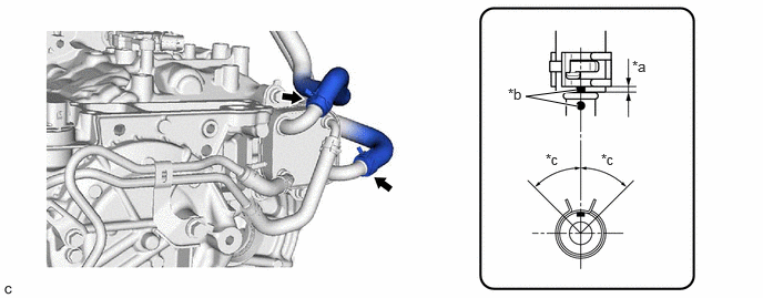
- Connect the water by-pass hose assembly to the transmission oil cooler and slide the 2 clips to secure it.
*a 2 to 7 mm (0.0787 to 0.276 in.) *b Paint Mark *c 45° (Claw of Clip Location) - - NOTE:- Make sure to slide the water by-pass hose assembly until it contacts the hose stopper of the transmission oil cooler.
- Make sure to align the paint mark of the water by-pass hose assembly with the paint mark of the transmission oil cooler.
- Make sure that the claws of the clip are within the location shown in the illustration.
- Connect the water by-pass hose assembly to the transmission oil cooler and slide the 2 clips to secure it.
- INSTALL TRANSMISSION BREATHER CLAMP
- Engage the 3 clamps to install the transmission breather clamp.
- INSTALL BATTERY CLAMP SUB-ASSEMBLY
Refer to PROCEDURE - Step 45
- INSTALL BATTERY
Refer to INSTALLATION [12/2019 - 10/2022]
- INSTALL AIR CLEANER ASSEMBLY WITH AIR CLEANER HOSE
Refer to PROCEDURE - Step 50
- INSTALL INLET AIR CLEANER ASSEMBLY
Refer to PROCEDURE - Step 51
- INSTALL COOL AIR INTAKE DUCT SEAL (for Sport Package)
Refer to PROCEDURE - Step 4
- INSTALL COOL AIR INTAKE DUCT SEAL (except Sport Package)
Refer to PROCEDURE - Step 4
- ADD ENGINE COOLANT
Refer to PROCEDURE - Step 2
- ADJUST AUTOMATIC TRANSAXLE FLUID
Refer to ADJUSTMENT [12/2019 - 10/2022]
- INSPECT FOR COOLANT LEAK
Refer to PROCEDURE - Step 1
- INSPECT FOR AUTOMATIC TRANSAXLE FLUID LEAK
- INSTALL FRONT FENDER APRON SEAL LH
Refer to PROCEDURE - Step 74
- INSTALL REAR ENGINE UNDER COVER LH
Refer to PROCEDURE - Step 79
- INSTALL NO. 1 ENGINE UNDER COVER
Refer to PROCEDURE - Step 80
- INSTALL FRONT WHEEL OPENING EXTENSION PAD LH
Refer to PROCEDURE - Step 81
- INSTALL FRONT WHEEL OPENING EXTENSION PAD RH
Refer to PROCEDURE - Step 82