Installation [12/2019 - 10/2022]: Procedure
- INSTALL VVT SENSOR (for Exhaust Side of Bank 2)
- Apply a light coat of engine oil to the O-ring of the VVT sensor.NOTE:
If reusing the VVT sensor, be sure to inspect the O-ring.
- Clean the bolt and bolt hole.
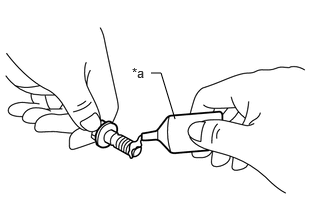
- Apply adhesive to 2 or 3 threads at the end of the bolt.
*a Adhesive Adhesive
Toyota Genuine Adhesive 1324, Three Bond 1324 or equivalent
- Install the VVT sensor to the cylinder head cover sub-assembly LH with the bolt.
Torque: 10 N.m (102 kgf/cm, 7 ft.lbf)
NOTE:- If the VVT sensor has been struck or dropped, replace it.
- Make sure that the O-ring is not cracked or moved out of place when installing the VVT sensor.
- Connect the VVT sensor connector.
- Apply a light coat of engine oil to the O-ring of the VVT sensor.
- INSTALL VVT SENSOR (for Intake Side of Bank 2)
- Apply a light coat of engine oil to the O-ring of the VVT sensor.NOTE:
If reusing the VVT sensor, be sure to inspect the O-ring.
- Clean the bolt and bolt hole.
- Apply adhesive to 2 or 3 threads at the end of the bolt.
*a Adhesive Adhesive
Toyota Genuine Adhesive 1324, Three Bond 1324 or equivalent
- Install the VVT sensor to the cylinder head cover sub-assembly LH with the bolt.
Torque: 10 N.m (102 kgf/cm, 7 ft.lbf)
NOTE:- If the VVT sensor has been struck or dropped, replace it.
- Make sure that the O-ring is not cracked or moved out of place when installing the VVT sensor.
- Connect the VVT sensor connector.
- Apply a light coat of engine oil to the O-ring of the VVT sensor.
- INSTALL VVT SENSOR (for Exhaust Side of Bank 1)
- Apply a light coat of engine oil to the O-ring of the VVT sensor.NOTE:
If reusing the VVT sensor, be sure to inspect the O-ring.
- Clean the bolt and bolt hole.
- Apply adhesive to 2 or 3 threads at the end of the bolt.
*a Adhesive Adhesive
Toyota Genuine Adhesive 1324, Three Bond 1324 or equivalent
- Install the VVT sensor to the cylinder head cover sub-assembly with the bolt.
Torque: 10 N.m (102 kgf/cm, 7 ft.lbf)
NOTE:- If the VVT sensor has been struck or dropped, replace it.
- Make sure that the O-ring is not cracked or moved out of place when installing the VVT sensor.
- Connect the VVT sensor connector.
- Apply a light coat of engine oil to the O-ring of the VVT sensor.
- INSTALL VVT SENSOR (for Intake Side of Bank 1)
- Apply a light coat of engine oil to the O-ring of the VVT sensor.NOTE:
If reusing the VVT sensor, be sure to inspect the O-ring.
- Clean the bolt and bolt hole.
- Apply adhesive to 2 or 3 threads at the end of the bolt.
*a Adhesive Adhesive
Toyota Genuine Adhesive 1324, Three Bond 1324 or equivalent
- Install the VVT sensor to the cylinder head cover sub-assembly with the bolt.
Torque: 10 N.m (102 kgf/cm, 7 ft.lbf)
NOTE:- If the VVT sensor has been struck or dropped, replace it.
- Make sure that the O-ring is not cracked or moved out of place when installing the VVT sensor.
- Connect the VVT sensor connector.
- Apply a light coat of engine oil to the O-ring of the VVT sensor.
- INSTALL INTAKE AIR SURGE TANK ASSEMBLY
Refer to INSTALLATION [12/2019 - 10/2022]
- INSPECT FOR ENGINE OIL LEAK
Refer to PROCEDURE - Step 6 [12/2019 - 09/2020] , or refer to PROCEDURE - Step 6 [09/2020 - 10/2021] , or refer to PROCEDURE - Step 6 [10/2021 - 10/2022]