Installation [10/2022 - ]: Procedure
- INSTALL KICK DOOR CONTROL SENSOR
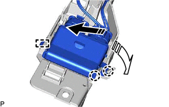
- Engage the guide and 2 claws as shown in the illustration.

Install in this Direction (1) 
Install in this Direction (2) NOTE:- Do not subject the kick door control sensor to a strong impact or drop it.
- Do not reuse a kick door control sensor which has been subjected to a strong impact or dropped.
- Be careful not to pull the wire harness.
- Be careful not to twist the wire harness.
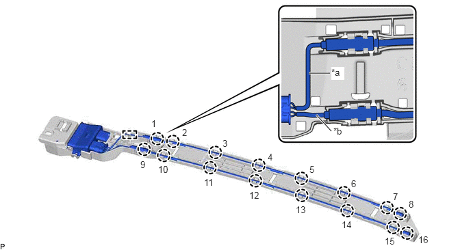
- Engage the guide and 16 claws as shown in the illustration.
*a Wire (Red) *b Wire (Black) NOTE:Fully insert the kick door control sensor into the kick door control bracket.
HINT:
Engage each claw in the order shown in the illustration.
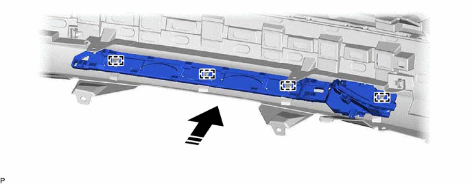
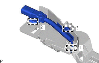
- Engage the 3 clamps to install the kick door control sensor.
 Courtesy of © TOYOTA, LICENSE AGREEMENT TMS1002
HINT:
Engage each clamp in the order shown in the illustration.
- Engage the guide and 2 claws as shown in the illustration.
- INSTALL KICK DOOR CONTROL SENSOR WITH BRACKET
- Engage the 4 guides as shown in the illustration.
Install in this Direction - - - Install the kick door control sensor with bracket with the 4 clips.
- Connect the connector.NOTE:
Do not touch the terminals of the kick door control sensor connector.
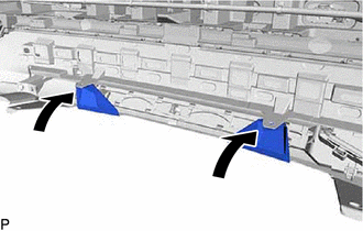
- Install the rear bumper assembly to its original position as shown in the illustration.
- Install the 2 clips.
- Engage the 4 guides as shown in the illustration.
- INSTALL REAR BUMPER ASSEMBLY
Refer to INSTALLATION [10/2022 - ]
- CONNECT CABLE TO NEGATIVE AUXILIARY BATTERY TERMINAL
for T24A-FTS:
Refer to PROCEDURE - Step 4 [10/2022 - 11/2023] , or refer to PROCEDURE - Step 4 [11/2023 - ]
for A25A-FXS:
Refer to PROCEDURE - Step 2 [12/2019 - 11/2023] , or refer to PROCEDURE - Step 2 [11/2023 - ]
- INSTALL BATTERY SERVICE HOLE COVER (for HV Model)
Refer to PROCEDURE - Step 3 [12/2019 - 11/2023] , or refer to PROCEDURE - Step 3 [11/2023 - ]
- INSPECT KICK DOOR CONTROL SENSOR
Refer to OPERATION CHECK [12/2019 - 11/2023] , or refer to OPERATION CHECK [11/2023 - ]