Adjustment [12/2019 - 10/2022]: Procedure
- INSPECT AND ADJUST BRAKE PEDAL HEIGHT
- Remove the front door scuff plate LH.
Refer to PROCEDURE - Step 9
- Remove the cowl side trim sub-assembly LH.
Refer to PROCEDURE - Step 10
- Remove the accelerator pedal pad.
Refer to PROCEDURE - Step 5
- Remove the accelerator pedal.
Refer to PROCEDURE - Step 6
- Check the brake pedal height.
HINT:
Inspect and adjust the brake pedal height with the floor carpet and front floor mat folded back.
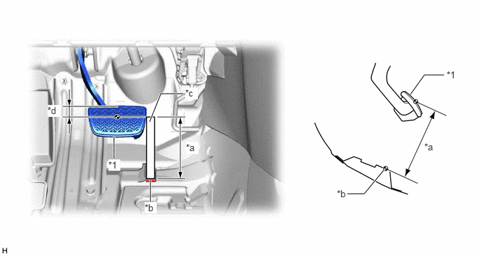
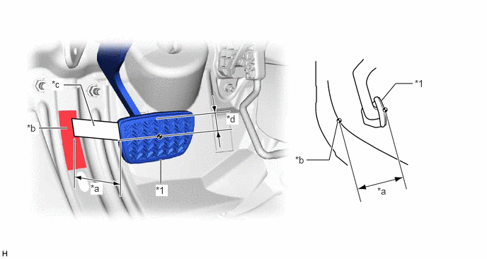
- Measure the shortest distance between the brake pedal pad surface and floor panel as shown in the illustration.
*1 Brake Pedal Pad - - *a Brake Pedal Height *b Measuring Plane of Floor Panel *c Ruler *d 36 mm (1.42 in.) Brake Pedal Height from Floor Panel
155.6 to 171.6 mm (6.13 to 6.76 in.)
HINT:
If the brake pedal height is not as specified, inspect and adjust the push rod length according to the procedure below.
- Measure the shortest distance between the brake pedal pad surface and floor panel as shown in the illustration.
- Adjust the push rod length.
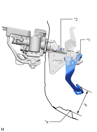
- Remove the stop light switch assembly.
*1 Stop Light Switch Assembly *2 Lock Nut *a Floor Panel *b Brake Pedal Height Refer to PROCEDURE - Step 4
- Loosen the lock nut.
- Adjust the brake pedal height by turning the push rod.
Brake Pedal Height from Floor Panel
155.6 to 171.6 mm (6.13 to 6.76 in.)
- Tighten the lock nut.
Torque: 25.5 N.m (260 kgf/cm, 19 ft.lbf)
- Install the stop light switch assembly.
Refer to PROCEDURE - Step 1
- Remove the stop light switch assembly.
- Install the accelerator pedal.
Refer to PROCEDURE - Step 1
- Install the accelerator pedal pad.
Refer to PROCEDURE - Step 2
- Install the cowl side trim sub-assembly LH.
Refer to PROCEDURE - Step 51
- Install the front door scuff plate LH.
Refer to PROCEDURE - Step 52
- Remove the front door scuff plate LH.
- INSPECT AND ADJUST BRAKE PEDAL STROKE SENSOR ASSEMBLY NOTE:
Do not depress the brake pedal after turning the ignition switch to ON.
- Inspect the brake pedal stroke sensor assembly.
- Read the stroke sensor value without the brake pedal depressed.
Chassis > Brake Booster > Data List
Tester Display Stroke Sensor Standard Voltage (without the brake pedal depressed)
0.8 to 1.2 V
HINT:
If the stroke sensor value is not within the standard voltage, adjust the brake pedal stroke sensor assembly.
- Read the stroke sensor value without the brake pedal depressed.
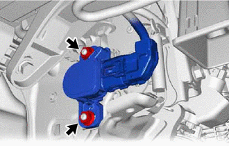
- Adjust the brake pedal stroke sensor assembly.
- Loosen the 2 nuts.
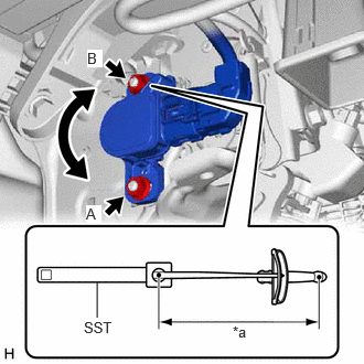
- Read the stroke sensor value in the Data List, and turn the brake pedal stroke sensor assembly slowly to the right or left to adjust the output voltage so that it is within the following range.
*a Torque Wrench Fulcrum Length Standard Voltage (without the brake pedal depressed)
0.8 to 1.2 V
- Fully tighten the nut (A).
Torque: 8.5 N.m (87 kgf/cm, 75 in.lbf)
- Using SST, fully tighten the nut (B).
- SST: 09961-00950
Specified tightening torque
Torque: 8.5 N.m (87 kgf/cm, 75 in.lbf)
HINT:
- Calculate the torque wrench reading when changing the fulcrum length of the torque wrench.
Refer to PRECAUTION [12/2019 - 11/2023]
- When using SST (fulcrum length of 150 mm (5.91 in.)) + torque wrench (fulcrum length of 185 mm (7.28 in.)):
4.7 N.m (48 kgf/cm, 42 in.lbf)
- Loosen the 2 nuts.
- Perform initialization and calibration.
Refer to UTILITY [12/2019 - 11/2023]
- Inspect the brake pedal stroke sensor assembly.
- INSPECT BRAKE PEDAL FREE PLAY
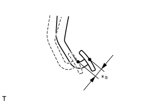
- Depress the brake pedal until a slight resistance is felt. Measure the distance as shown in the illustration.
*a Brake Pedal Free Play Brake Pedal Free Play
1.0 to 6.0 mm (0.0394 to 0.236 in.)
HINT:
- If the brake pedal free play is not as specified, check the stop light switch clearance.
Refer to PROCEDURE - Step 1
- If the brake pedal free play is as specified, proceed to the Inspect Brake Pedal Reserve Distance procedure.
- If the brake pedal free play is not as specified, check the stop light switch clearance.
- Depress the brake pedal until a slight resistance is felt. Measure the distance as shown in the illustration.
- INSPECT BRAKE PEDAL RESERVE DISTANCE
- With the ignition switch ON (READY), depress the brake pedal and measure the brake pedal reserve distance.
*1 Brake Pedal Pad - - *a Brake Pedal Reserve Distance *b Measuring Plane of Floor Panel *c Ruler *d 36 mm (1.42 in.) Brake Pedal Reserve Distance from Floor Panel at 300 N (31 kgf, 67.4 lbf)
91 mm (3.58 in.) or more
HINT:
If the distance is not as specified, troubleshoot the brake system.
Refer to PROBLEM SYMPTOMS TABLE [12/2019 - ]
- With the ignition switch ON (READY), depress the brake pedal and measure the brake pedal reserve distance.