Installation [12/2019 - 10/2022]: Procedure
- INSTALL VACUUM PUMP ASSEMBLY
- Clean the vacuum pump assembly installation bolt holes in the camshaft housing sub-assembly and cylinder head sub-assembly.
- When using a new vacuum pump assembly:
- When reusing the vacuum pump assembly:
- Apply engine oil to the inner surface of the installation hole.
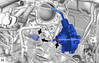
- Temporarily install the vacuum pump assembly so that the oil pipe engages with the hole of the camshaft and the coupling teeth engage with the groove of the camshaft.
*a Coupling Teeth *b Groove *c Oil Pipe 
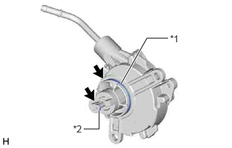
Install in this Direction NOTE:- Ensure that the vacuum pump assembly is installed securely.
- Be careful not to pinch the O-ring.
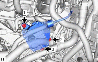
- Install the vacuum pump assembly with 3 new bolts.
 Courtesy of © TOYOTA, LICENSE AGREEMENT TMS1002
Torque: 21 N.m (214 kgf/cm, 15 ft.lbf)
NOTE:- After installation, check that there are no gaps between the matching surfaces and that the vacuum pump assembly is not installed at an angle.
- Tighten the 3 bolts in the order shown in the illustration.
- CONNECT AIR TUBE
- Connect the air tube to the vacuum pump assembly and slide the clip to secure it.
- INSTALL ENGINE WIRE
- Install the earth wire with the bolt.
Torque: 10 N.m (102 kgf/cm, 7 ft.lbf)
- Install the engine wire with the 2 bolts.
Torque: 10 N.m (102 kgf/cm, 7 ft.lbf)
- Install the earth wire with the bolt.
- INSTALL BREATHER PLUG HOSE
- Engage the clamp to install the breather plug hose.
- INSTALL VACUUM HOSE SUB-ASSEMBLY
- Engage the clamp to install the vacuum hose sub-assembly.
- INSTALL INLET HEATER WATER HOSE B
- Engage the clamp to install the inlet heater water hose B.
- INSTALL NO. 2 SURGE TANK STAY
- Install the No. 2 surge tank stay with the 2 bolts.
Torque: 21 N.m (214 kgf/cm, 15 ft.lbf)
- Install the No. 2 surge tank stay with the 2 bolts.
- INSTALL THROTTLE BODY WITH MOTOR ASSEMBLY
Refer to INSTALLATION [12/2019 - 10/2022]
- INSTALL BATTERY CLAMP SUB-ASSEMBLY
- Install the battery clamp sub-assembly with the 3 bolts and nut.
Bolt
Torque: 18.5 N.m (189 kgf/cm, 14 ft.lbf)
Nut
Torque: 8.0 N.m (82 kgf/cm, 71 in.lbf)
- Engage the 5 clamps to the battery clamp sub-assembly.
- Install the battery clamp sub-assembly with the 3 bolts and nut.
- INSTALL AIR CLEANER ASSEMBLY WITH AIR CLEANER HOSE
Refer to PROCEDURE - Step 50 [12/2019 - 09/2020] , or refer to PROCEDURE - Step 50 [09/2020 - 10/2022]
- INSTALL BATTERY
Refer to INSTALLATION [12/2019 - 10/2022]
- INSPECT VACUUM PUMP OPERATION