Removal [12/2019 - 10/2022]: Procedure
- REMOVE FRONT WHEEL OPENING EXTENSION PAD LH
Refer to PROCEDURE - Step 8 [12/2019 - 09/2020] , or refer to PROCEDURE - Step 8 [09/2020 - 10/2022]
- REMOVE FRONT WHEEL OPENING EXTENSION PAD RH
Refer to PROCEDURE - Step 9 [12/2019 - 09/2020] , or refer to PROCEDURE - Step 9 [09/2020 - 10/2022]
- REMOVE NO. 1 ENGINE UNDER COVER
Refer to PROCEDURE - Step 10 [12/2019 - 09/2020] , or refer to PROCEDURE - Step 10 [09/2020 - 10/2022]
- REMOVE REAR ENGINE UNDER COVER LH
Refer to PROCEDURE - Step 11 [12/2019 - 09/2020] , or refer to PROCEDURE - Step 11 [09/2020 - 10/2022]
- REMOVE REAR ENGINE UNDER COVER RH
Refer to PROCEDURE - Step 12 [12/2019 - 09/2020] , or refer to PROCEDURE - Step 12 [09/2020 - 10/2022]
- DRAIN ENGINE COOLANT
Refer to PROCEDURE - Step 1
- REMOVE V-BANK COVER SUB-ASSEMBLY
Refer to PROCEDURE - Step 23 [12/2019 - 09/2020] , or refer to PROCEDURE - Step 23 [09/2020 - 10/2022]
- REMOVE NO. 2 ENGINE MOUNTING STAY RH
Refer to PROCEDURE - Step 20
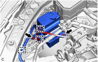
- SEPARATE RADIATOR RESERVE TANK ASSEMBLY
- REMOVE ENGINE MOUNTING INSULATOR SUB-ASSEMBLY RH
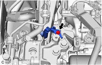
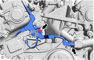
- Disconnect the water inlet with thermostat sub-assembly connector.
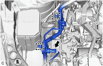
- Disengage the 2 clamps to separate the suction hose sub-assembly, suction pipe sub-assembly and air conditioning tube and accessory assembly.
- Remove the bolt to disconnect the No. 2 earth wire from the engine mounting insulator sub-assembly RH.
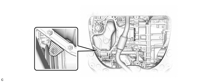
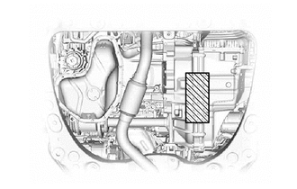
- Using a safety stand, support the engine assembly with transaxle at the position shown in the illustration.

Support Area - - NOTE:- Make sure to firmly support the weight of the engine assembly and automatic transaxle assembly before removing the engine mounting insulator sub-assembly RH.
- Do not place the safety stand under the oil pan.
- Support the engine assembly with automatic transaxle assembly at the position shown in the illustration to stabilize it.
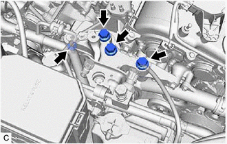
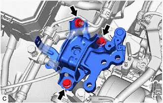
Support Area Remove the 3 bolts and nut to separate the engine mounting insulator sub-assembly RH from the front No. 1 engine mounting bracket LH.
- Remove the nut, 2 bolts and engine mounting insulator sub-assembly RH from the engine mounting spacer and vehicle body.
- Disconnect the water inlet with thermostat sub-assembly connector.
- DISCONNECT ENGINE WIRE
- REMOVE REAR ENGINE MOUNTING STAY RH
Refer to PROCEDURE - Step 21
- REMOVE FRONT NO. 1 ENGINE MOUNTING BRACKET LH
Refer to PROCEDURE - Step 6
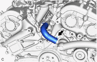
- DISCONNECT WATER BY-PASS HOSE
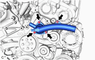
- REMOVE WATER INLET WITH THERMOSTAT SUB-ASSEMBLY