Disassembly [12/2019 - 10/2022]: Procedure
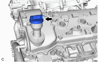
- REMOVE OIL FILLER CAP SUB-ASSEMBLY
- REMOVE SPARK PLUG
Refer to PROCEDURE - Step 3
- REMOVE PCV VALVE (VENTILATION VALVE SUB-ASSEMBLY)
Refer to PROCEDURE - Step 3
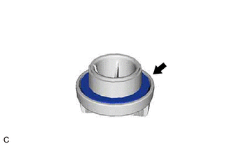
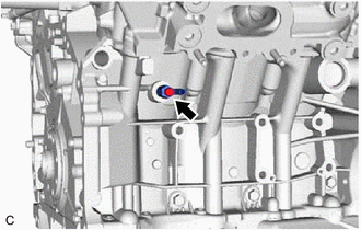
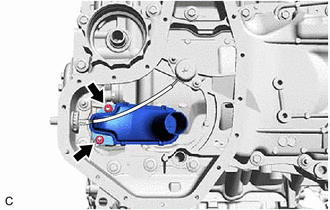
- REMOVE CYLINDER BLOCK WATER DRAIN COCK SUB-ASSEMBLY
- Remove the cylinder block water drain cock plug from the cylinder block water drain cock sub-assembly.
- Remove the cylinder block water drain cock sub-assembly from the cylinder block sub-assembly.
- REMOVE CRANKSHAFT PULLEY
Refer to PROCEDURE - Step 3
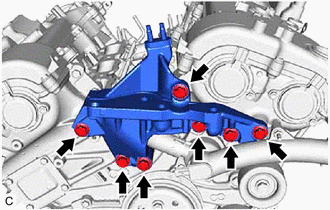
- REMOVE FRONT NO. 1 ENGINE MOUNTING BRACKET LH
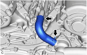
- REMOVE WATER BY-PASS HOSE
- REMOVE WATER INLET WITH THERMOSTAT SUB-ASSEMBLY
Refer to PROCEDURE - Step 15
- REMOVE CAMSHAFT TIMING OIL CONTROL SOLENOID ASSEMBLY (for Intake Side of Bank 1)
Refer to PROCEDURE - Step 3
- REMOVE CAMSHAFT TIMING OIL CONTROL SOLENOID ASSEMBLY (for Exhaust Side of Bank 1)
Refer to PROCEDURE - Step 5
- REMOVE CAMSHAFT TIMING OIL CONTROL SOLENOID ASSEMBLY (for Exhaust Side of Bank 2)
Refer to PROCEDURE - Step 2
- REMOVE CAMSHAFT TIMING OIL CONTROL SOLENOID ASSEMBLY (for Intake Side of Bank 2)
Refer to PROCEDURE - Step 7
- REMOVE VVT SENSOR (for Intake Side of Bank 1)
Refer to PROCEDURE - Step 2
- REMOVE VVT SENSOR (for Exhaust Side of Bank 1)
Refer to PROCEDURE - Step 3
- REMOVE VVT SENSOR (for Intake Side of Bank 2)
Refer to PROCEDURE - Step 4
- REMOVE VVT SENSOR (for Exhaust Side of Bank 2)
Refer to PROCEDURE - Step 5
- REMOVE CRANKSHAFT POSITION SENSOR PROTECTOR
Refer to PROCEDURE - Step 2
- REMOVE CRANKSHAFT POSITION SENSOR
Refer to PROCEDURE - Step 3
- REMOVE OIL COOLER ASSEMBLY
Refer to PROCEDURE - Step 4
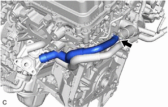
- REMOVE NO. 4 WATER BY-PASS HOSE
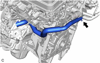
- REMOVE NO. 5 WATER BY-PASS HOSE
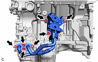
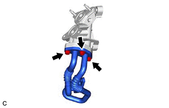
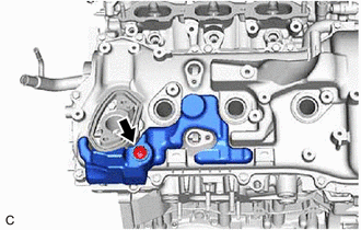
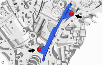
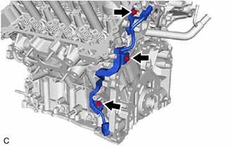
- REMOVE OIL COOLER PIPE
- Remove the 4 bolts, 3 nuts and oil cooler pipe with No. 1 oil cooler bracket and oil hole cover gasket from the cylinder block sub-assembly and oil pan sub-assembly.
Remove the 3 bolts, oil cooler pipe and oil cooler gasket from the No. 1 oil cooler bracket.
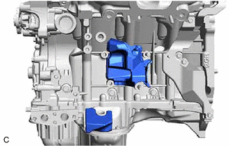
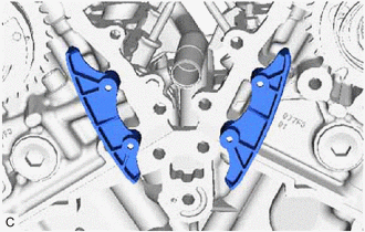
- Remove the No. 2 cylinder block insulator and No. 3 cylinder block insulator from the cylinder block sub-assembly and oil pan sub-assembly.
- Remove the 4 bolts, 3 nuts and oil cooler pipe with No. 1 oil cooler bracket and oil hole cover gasket from the cylinder block sub-assembly and oil pan sub-assembly.
- REMOVE ENGINE COOLANT TEMPERATURE SENSOR
Refer to PROCEDURE - Step 3
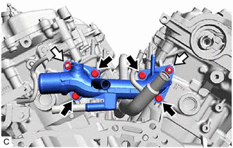
- REMOVE WATER OUTLET
- w/ Stud Bolt:

Bolt 
Bolt or Nut - Remove the 4 bolts, 2 nuts and water outlet from the cylinder head sub-assembly and cylinder head LH.
- w/o Stud Bolt:
- Remove the 6 bolts and water outlet from the cylinder head sub-assembly and cylinder head LH.
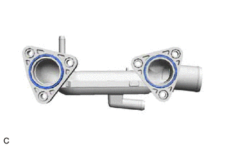
- Remove the 2 No. 2 water inlet housing gaskets from the water outlet.
- w/ Stud Bolt:
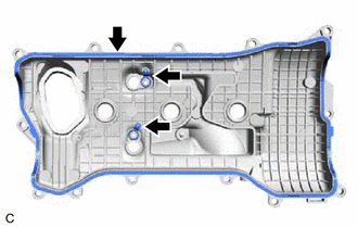
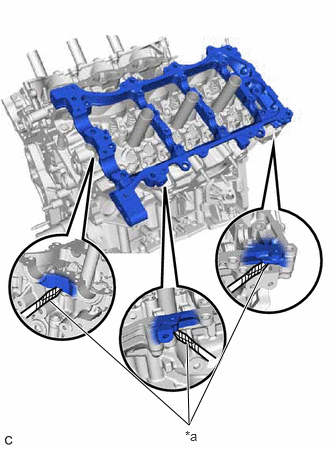
- REMOVE CYLINDER HEAD COVER SUB-ASSEMBLY
Remove the clip and No. 1 engine cover sub-assembly from the cylinder head cover sub-assembly.
- Remove the 13 bolts and cylinder head cover sub-assembly from the camshaft housing sub-assembly.
- Remove the camshaft bearing cap oil hole gasket from the camshaft bearing cap.
- Remove the 3 cylinder head cover gaskets from the cylinder head cover sub-assembly.
- REMOVE CYLINDER HEAD COVER SUB-ASSEMBLY LH
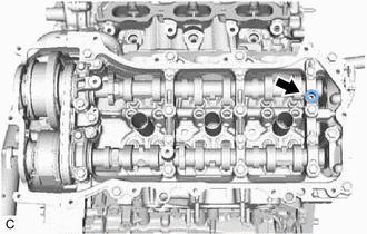
Remove the 2 No. 1 V-bank cover brackets from the cylinder head cover sub-assembly LH.
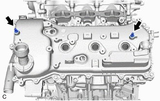
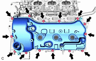
- Remove the 14 bolts and cylinder head cover sub-assembly LH from the camshaft housing sub-assembly LH.
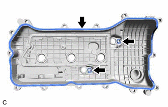
Remove the camshaft bearing cap oil hole gasket LH from the camshaft bearing cap.
Remove the 3 No. 2 cylinder head cover gaskets from the cylinder head cover sub-assembly LH.
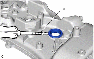
- REMOVE SPARK PLUG TUBE GASKET
- REMOVE OIL PAN DRAIN PLUG
- REMOVE OIL FILTER CAP ASSEMBLY
Refer to PROCEDURE - Step 3 [12/2019 - 09/2020] , or refer to PROCEDURE - Step 3 [09/2020 - 10/2021] , or refer to PROCEDURE - Step 3 [10/2021 - 10/2022]
- REMOVE ENGINE OIL PRESSURE SWITCH ASSEMBLY
Refer to PROCEDURE - Step 3
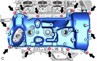
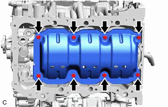
- REMOVE NO. 2 OIL PAN SUB-ASSEMBLY
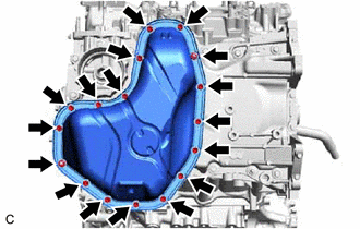
- Remove the 15 bolts and 2 nuts from the No. 2 oil pan sub-assembly.
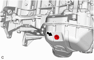
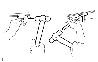
- Insert the blade of an oil pan seal cutter between the oil pan sub-assembly and No. 2 oil pan sub-assembly. Cut through the applied sealer and remove the No. 2 oil pan sub-assembly.NOTE:
Be careful not to damage the contact surfaces of the oil pans.
- Remove the 15 bolts and 2 nuts from the No. 2 oil pan sub-assembly.
- REMOVE OIL STRAINER SUB-ASSEMBLY
- REMOVE ENGINE OIL LEVEL SENSOR
Refer to PROCEDURE - Step 5
- REMOVE OIL PAN SUB-ASSEMBLY
Refer to PROCEDURE - Step 37
- REMOVE OIL FILTER BRACKET CLIP
- REMOVE NO. 1 OIL PAN BAFFLE PLATE
- REMOVE TIMING CHAIN COVER PLATE
- REMOVE TIMING CHAIN CASE OIL SEAL
Refer to PROCEDURE - Step 4
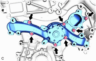
- REMOVE TIMING CHAIN COVER ASSEMBLY
Refer to PROCEDURE - Step 3
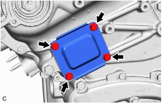
- REMOVE ENGINE WATER PUMP ASSEMBLY
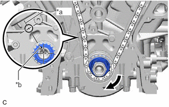
- SET NO. 1 CYLINDER TO TDC (COMPRESSION)
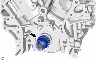
- Temporarily tighten the crankshaft pulley set bolt to the crankshaft.
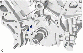
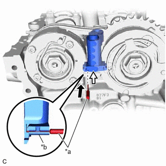
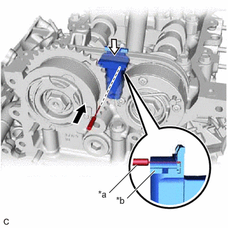
- Turn the crankshaft clockwise to align the timing mark of the crankshaft timing sprocket key groove chase position with the center line of the block bore (for Bank 1) (TDC / compression).
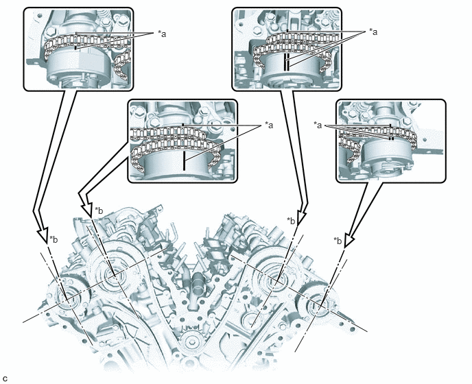
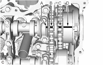
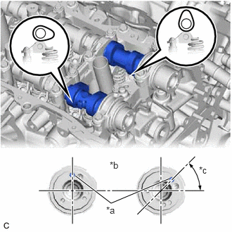
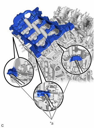
*a Center Line *b Key Groove - Check that the timing marks of the camshaft timing gear assembly and camshaft timing exhaust gear assembly are aligned with the timing marks of the camshaft bearing caps as shown in the illustration.
*a Timing Mark *b Viewpoint NOTE:- Check each timing mark from a viewpoint directly in line with the center of the camshaft and the timing mark on each camshaft timing gear assembly and each camshaft timing exhaust gear assembly.
- If the timing marks are checked from any other viewpoint, the valve timing may appear misaligned.
HINT:
- If not aligned, turn the crankshaft 1 revolution (360°) clockwise and align the timing marks as shown in the illustration.
- For the camshaft or No. 3 camshaft sub-assembly:
Be sure to check the mark (A) at the point where the marks (B), (C) and (D) are positioned in line. If the marks are checked from any other viewpoint, they cannot be checked correctly.
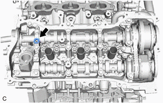
- REMOVE NO. 1 CHAIN TENSIONER ASSEMBLY
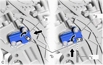
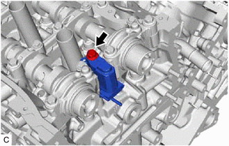
- Turn the stopper plate clockwise to release the lock, and push the plunger deep into the No. 1 chain tensioner assembly.
*a Plunger *b Stopper Plate *c Pin - Turn the stopper plate counterclockwise to set the lock, and insert a 1.0 mm (0.0394 in.) diameter pin into the hole of the stopper plate.
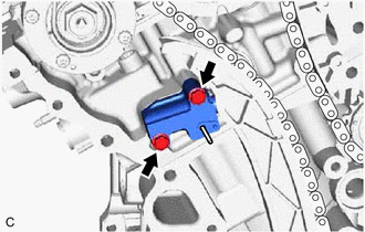
- Remove the 2 bolts and No. 1 chain tensioner assembly from the cylinder head sub-assembly.
- Turn the stopper plate clockwise to release the lock, and push the plunger deep into the No. 1 chain tensioner assembly.
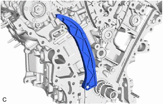
- REMOVE CHAIN TENSIONER SLIPPER
- REMOVE CHAIN SUB-ASSEMBLY
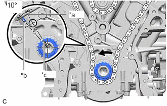
- Turn the crankshaft 10° counterclockwise to loosen the chain sub-assembly of the crankshaft timing sprocket.
*a Center Line *b Mark *c Key Groove - Remove the crankshaft pulley set bolt from the crankshaft.
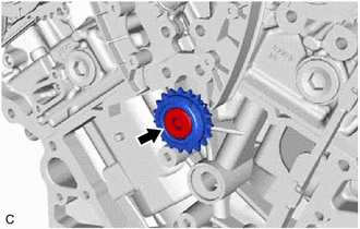
- Remove the chain sub-assembly from the crankshaft timing sprocket and place it on the crankshaft.
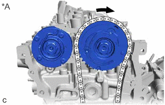
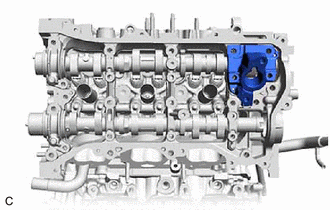
- Turn the camshaft timing gear assembly on bank 1 clockwise (approximately 60°) so that it is positioned as shown in the illustration.
*A for Bank 1 NOTE:Be sure to loosen the chain sub-assembly between the banks.
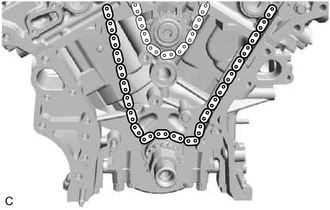
- Remove the chain sub-assembly from the engine assembly.
- Turn the crankshaft 10° counterclockwise to loosen the chain sub-assembly of the crankshaft timing sprocket.
- REMOVE IDLE SPROCKET ASSEMBLY
- REMOVE NO. 1 CHAIN VIBRATION DAMPER
- REMOVE NO. 2 CHAIN VIBRATION DAMPER
- REMOVE CRANKSHAFT TIMING SPROCKET
- REMOVE CRANKSHAFT TIMING GEAR KEY
- REMOVE CAMSHAFT TIMING GEAR ASSEMBLY, CAMSHAFT TIMING EXHAUST GEAR ASSEMBLY AND NO. 2 CHAIN SUB-ASSEMBLY (for Bank 1)
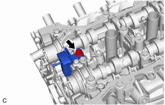
- While raising the No. 2 chain tensioner assembly, insert a 1.0 mm (0.0394 in.) diameter pin into the hole to secure the No. 2 chain tensioner assembly.
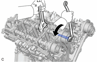
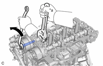
*a Pin *b Plunger Push - Using a wrench to hold the hexagonal portion of camshaft, loosen the camshaft timing gear bolt of the camshaft timing gear assembly.NOTE:
- Be careful not to damage the camshaft, camshaft housing sub-assembly or spark plug tube with wrench.
- Do not loosen any other bolt. If any other bolt is loosened, replace the camshaft timing gear assembly and/or the camshaft timing exhaust gear assembly with a new one.
- If the camshaft timing gear bolt has been struck or dropped, replace it.
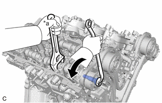
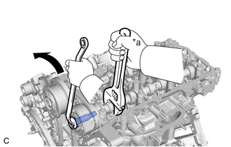
*a Hold Turn - Using a wrench to hold the hexagonal portion of No. 2 camshaft, loosen the camshaft timing gear bolt of the camshaft timing exhaust gear assembly.NOTE:
- Be careful not to damage the No. 2 camshaft, camshaft housing sub-assembly or spark plug tube with wrench.
- Do not loosen any other bolt. If any other bolt is loosened, replace the camshaft timing gear assembly and/or the camshaft timing exhaust gear assembly with a new one.
- If the camshaft timing gear bolt has been struck or dropped, replace it.
*a Hold Turn - Remove the 2 camshaft timing gear bolts, camshaft timing gear assembly and camshaft timing exhaust gear assembly together with the No. 2 chain sub-assembly.
- While raising the No. 2 chain tensioner assembly, insert a 1.0 mm (0.0394 in.) diameter pin into the hole to secure the No. 2 chain tensioner assembly.
- REMOVE NO. 2 CHAIN TENSIONER ASSEMBLY
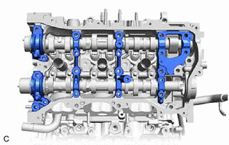
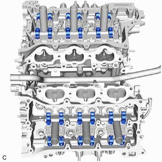
- REMOVE CAMSHAFT BEARING CAP (for Bank 1)
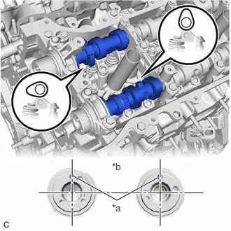
- Check that the camshaft and No. 2 camshaft are positioned as shown in the illustration.
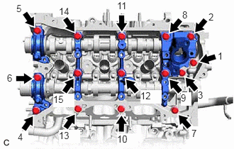
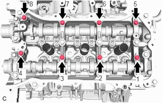
*a Straight Pin *b Front View *c 45° - Uniformly loosen and remove the 9 bolts in several steps in the order shown in the illustration.
- Uniformly loosen and remove the 15 bolts in several steps in the order shown in the illustration.NOTE:
Make sure that the camshaft and No. 2 camshaft remain level while uniformly loosening the bolts.
- Remove the fuel pump lifter housing from the camshaft housing sub-assembly.
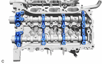
- Remove the 5 camshaft bearing caps from the camshaft housing sub-assembly.
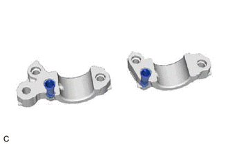
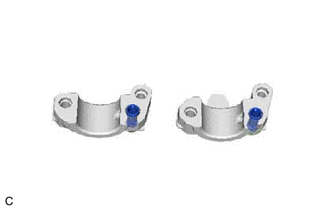
- Remove the 2 oil control valve filters from the 2 camshaft bearing caps.
- Check that the camshaft and No. 2 camshaft are positioned as shown in the illustration.
- REMOVE CAMSHAFT
- Remove the camshaft from the camshaft housing sub-assembly.
- REMOVE NO. 2 CAMSHAFT
- Remove the No. 2 camshaft from the camshaft housing sub-assembly.
- REMOVE CAMSHAFT HOUSING SUB-ASSEMBLY
- Remove the camshaft housing sub-assembly by prying between the cylinder head sub-assembly and camshaft housing sub-assembly with a screwdriver with its tip wrapped with protective tape.
*a Protective Tape NOTE:Be careful not to damage the contact surfaces of the cylinder head sub-assembly and camshaft housing sub-assembly.
- Remove the camshaft housing sub-assembly by prying between the cylinder head sub-assembly and camshaft housing sub-assembly with a screwdriver with its tip wrapped with protective tape.
- REMOVE CAMSHAFT TIMING GEAR ASSEMBLY, CAMSHAFT TIMING EXHAUST GEAR ASSEMBLY AND NO. 2 CHAIN SUB-ASSEMBLY (for Bank 2)
- While pushing down the No. 3 chain tensioner assembly, insert a 1.0 mm (0.0394 in.) diameter pin into the hole to secure the No. 3 chain tensioner assembly.
*a Pin *b Plunger Push - Using a wrench to hold the hexagonal portion of No. 3 camshaft sub-assembly, loosen the camshaft timing gear bolt of the camshaft timing gear assembly.
*a Hold Turn NOTE:- Be careful not to damage the No. 3 camshaft sub-assembly, camshaft housing sub-assembly LH or spark plug tube with wrench.
- Do not loosen any other bolt. If any other bolt is loosened, replace the camshaft timing gear assembly and/or the camshaft timing exhaust gear assembly with a new one.
- If the camshaft timing gear bolt has been struck or dropped, replace it.
- Using a wrench to hold the hexagonal portion of No. 4 camshaft sub-assembly, loosen the camshaft timing gear bolt of the camshaft timing exhaust gear assembly.NOTE:
- Be careful not to damage the No. 4 camshaft sub-assembly, camshaft housing sub-assembly LH or spark plug tube with wrench.
- Do not loosen any other bolt. If any other bolt is loosened, replace the camshaft timing gear assembly and/or the camshaft timing exhaust gear assembly with a new one.
- If the camshaft timing gear bolt has been struck or dropped, replace it.
*a Hold Turn - Remove the 2 camshaft timing gear bolts, camshaft timing gear assembly and camshaft timing exhaust gear assembly together with the No. 2 chain sub-assembly.
- While pushing down the No. 3 chain tensioner assembly, insert a 1.0 mm (0.0394 in.) diameter pin into the hole to secure the No. 3 chain tensioner assembly.
- REMOVE NO. 3 CHAIN TENSIONER ASSEMBLY
- REMOVE CAMSHAFT BEARING CAP (for Bank 2)
- Check that the No. 3 camshaft sub-assembly and No. 4 camshaft sub-assembly are positioned as shown in the illustration.
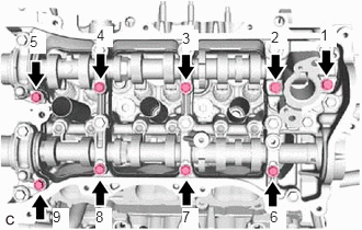
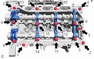
*a Straight Pin *b Front View - Uniformly loosen and remove the 8 bolts in several steps in the order shown in the illustration.
- Uniformly loosen and remove the 15 bolts in several steps in the order shown in the illustration.
NOTE:
Make sure that the No. 3 camshaft sub-assembly and No. 4 camshaft sub-assembly remain level while uniformly loosening the bolts.
- Remove the 5 camshaft bearing caps from the camshaft housing sub-assembly LH.
Remove the 2 oil control valve filters from the 2 camshaft bearing caps.
- Check that the No. 3 camshaft sub-assembly and No. 4 camshaft sub-assembly are positioned as shown in the illustration.
- REMOVE NO. 3 CAMSHAFT SUB-ASSEMBLY
- Remove the No. 3 camshaft sub-assembly from the camshaft housing sub-assembly LH.
- REMOVE NO. 4 CAMSHAFT SUB-ASSEMBLY
- Remove the No. 4 camshaft sub-assembly from the camshaft housing sub-assembly LH.
- REMOVE CAMSHAFT HOUSING SUB-ASSEMBLY LH
- Remove the camshaft housing sub-assembly LH by prying between the cylinder head LH and camshaft housing sub-assembly LH with a screwdriver with its tip wrapped with protective tape.
*a Protective Tape NOTE:Be careful not to damage the contact surfaces of the cylinder head LH and camshaft housing sub-assembly LH.
- Remove the camshaft housing sub-assembly LH by prying between the cylinder head LH and camshaft housing sub-assembly LH with a screwdriver with its tip wrapped with protective tape.
- REMOVE NO. 1 VALVE ROCKER ARM SUB-ASSEMBLY
- REMOVE VALVE LASH ADJUSTER ASSEMBLY
- REMOVE VALVE STEM CAP
- REMOVE SENSOR WIRE
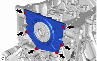
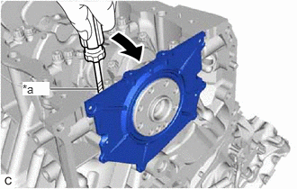
- REMOVE REAR ENGINE OIL SEAL RETAINER
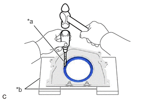
- REMOVE REAR ENGINE OIL SEAL
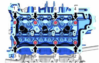
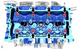
- REMOVE CYLINDER HEAD SUB-ASSEMBLY
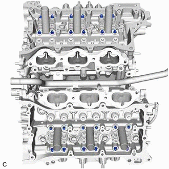
- Using a 10 mm bi-hexagon socket wrench, uniformly loosen the 8 cylinder head set bolts in several steps in the order shown in the illustration. Remove the 8 cylinder head set bolts and 8 cylinder head set plate washers.
NOTE:
- Be careful not to drop the cylinder head set plate washers into the cylinder head sub-assembly.
- Warpage or cracking of the cylinder head sub-assembly may result from removing the cylinder head set bolts in the incorrect order.
HINT:
Arrange the removed parts in such a way that they can be reinstalled to their original locations.
- Remove the cylinder head sub-assembly from the cylinder block sub-assembly.
- Using a 10 mm bi-hexagon socket wrench, uniformly loosen the 8 cylinder head set bolts in several steps in the order shown in the illustration. Remove the 8 cylinder head set bolts and 8 cylinder head set plate washers.
- REMOVE CYLINDER HEAD GASKET
Refer to PROCEDURE - Step 64
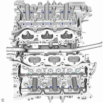
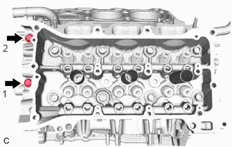
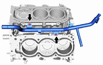
- REMOVE CYLINDER HEAD LH
- Uniformly loosen and remove the 2 bolts in several steps in the order shown in the illustration.
- Using a 10 mm bi-hexagon socket wrench, uniformly loosen the 8 cylinder head set bolts in several steps in the order shown in the illustration. Remove the 8 cylinder head set bolts and 8 cylinder head set plate washers.
NOTE:
- Be careful not to drop the cylinder head set plate washers into the cylinder head LH.
- Warpage or cracking of the cylinder head LH may result from removing the cylinder head set bolts in the incorrect order.
HINT:
Arrange the removed parts in such a way that they can be reinstalled to their original locations.
- Remove the cylinder head LH from the cylinder block sub-assembly.
- REMOVE NO. 2 CYLINDER HEAD GASKET
Refer to PROCEDURE - Step 66
- REMOVE WATER INLET PIPE
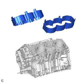
- REMOVE CYLINDER BLOCK WATER JACKET SPACER
- REMOVE STRAIGHT PIN
HINT:
It is not necessary to remove the straight pins unless they are being replaced.
- REMOVE CAMSHAFT BEARING CAP SETTING RING PIN
HINT:
It is not necessary to remove the camshaft bearing cap setting ring pins unless they are being replaced.
- REMOVE STUD BOLT
HINT:
If a stud bolt is deformed or its threads are damaged, replace it.