Installation [12/2019 - 10/2021]: Procedure
WARNING: This page is about a different variant/trim than selected.
- INSTALL VACUUM HOSE
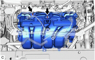
- Install the vacuum hose to the intake manifold.
- INSTALL NO. 1 ENGINE COVER
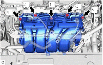
- Install the No. 1 engine cover with the clip.
- INSTALL NO. 1 INTAKE MANIFOLD TO HEAD GASKET
- Install a new No. 1 intake manifold to head gasket to the intake manifold.
- INSTALL INTAKE MANIFOLD
- w/o Stud Bolt:
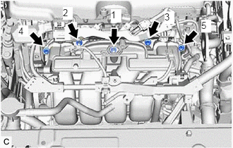
- Temporarily install the intake manifold to the cylinder head sub-assembly with the 5 bolts.
- Tighten the 5 bolts in the order shown in the illustration.
Torque: 24 N.m (245 kgf/cm, 18 ft.lbf)
- w/ Stud Bolt:
- Temporarily install the intake manifold to the cylinder head sub-assembly.
- Using an E8 "TORX" socket wrench, install the 2 stud bolts.
Torque: 6.5 N.m (66 kgf/cm, 58 in.lbf)
- Temporarily install the 3 bolts and 2 nuts.
- Tighten the 3 bolts and 2 nuts in the order shown in the illustration.
Torque: 24 N.m (245 kgf/cm, 18 ft.lbf)
- Temporarily install the intake manifold to the cylinder head sub-assembly.
- w/o Stud Bolt:
- INSTALL NO. 2 FUEL VAPOR FEED HOSE
- Install the No. 2 fuel vapor feed hose to the intake manifold.
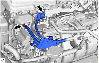
- INSTALL NO. 2 WATER BY-PASS PIPE
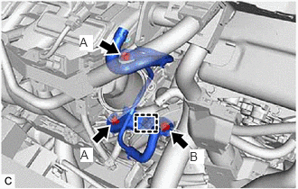
- Temporarily install the No. 2 water by-pass pipe to the cylinder block sub-assembly with the bolt (B).
- Using an 8 mm socket wrench, temporarily install the No. 2 water by-pass pipe to the intake manifold with the 2 bolts (A).
- Tighten the bolt (B).
Torque: 21 N.m (214 kgf/cm, 15 ft.lbf)
- Using an 8 mm socket wrench, tighten the 2 bolts (A).
Torque: 10 N.m (102 kgf/cm, 7 ft.lbf)
- Engage the wire harness clamp to connect the HV air conditioning wire.
- Temporarily install the No. 2 water by-pass pipe to the cylinder block sub-assembly with the bolt (B).
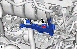
- CONNECT NO. 3 WATER BY-PASS PIPE
- Using an 8 mm socket wrench, connect the No. 3 water by-pass pipe to the intake manifold with the bolt.
Torque: 10 N.m (102 kgf/cm, 7 ft.lbf)
- Connect the No. 5 water by-pass hose to the No. 3 water by-pass pipe and slide the clip to secure it.
- Using an 8 mm socket wrench, connect the No. 3 water by-pass pipe to the intake manifold with the bolt.
- CONNECT ENGINE WIRE
- INSTALL PURGE VALVE (PURGE VSV)
Refer to INSTALLATION [12/2019 - ]
- INSTALL E.F.I. VACUUM SENSOR ASSEMBLY (MANIFOLD ABSOLUTE PRESSURE SENSOR)
Refer to PROCEDURE - Step 1
- INSTALL EGR VALVE ASSEMBLY
Refer to INSTALLATION [12/2019 - 10/2021]
- INSTALL THROTTLE BODY WITH MOTOR ASSEMBLY
Refer to INSTALLATION [12/2019 - 09/2020] , or refer to INSTALLATION [09/2020 - ]