DTC P0A9B-2A: Hybrid/EV Battery Temperature Sensor "A" Signal Stuck In Range; DTC P0AC5-2A: Hybrid/EV Battery Temperature Sensor "B" Signal Stuck In Range; DTC P0ACA-2A: Hybrid/EV Battery Temperature Sensor "C" Signal Stuck In Range; DTC P0AE8-2A: Hybrid/EV Battery Temperature Sensor "D" Signal Stuck In Range; DTC P0BC2-2A: Hybrid/EV Battery Temperature Sensor "E" Signal Stuck In Range; DTC P0C33-2A: Hybrid/EV Battery Temperature Sensor "F" Signal Stuck In Range; DTC P3065-62: Hybrid/EV Battery Temperature Sensor "Group 1" Signal Compare Failure; DTC P306A-62: Hybrid/EV Battery Temperature Sensor "Group 2" Signal Compare Failure [12/2019 - 11/2023]: Procedure
- CHECK DTC OUTPUT (HYBRID CONTROL)
- Check for DTCs.
Powertrain > Hybrid Control > Trouble Codes
Result
Result Proceed to P0AFC-00 or P0AFC-96 is not output. A P0AFC-00 or P0AFC-96 is also output. B - Turn the ignition switch off.
Result:
B
GO TO DTC CHART (HYBRID CONTROL SYSTEM). Refer to DIAGNOSTIC TROUBLE CODE CHART [12/2019 - 09/2020] , or refer to DIAGNOSTIC TROUBLE CODE CHART [09/2020 - 10/2021] , or refer to DIAGNOSTIC TROUBLE CODE CHART [10/2021 - 11/2023]
Result:
A
See step 2
- Check for DTCs.
- CHECK INSTALLATION OF TEMPERATURE SENSOR (HYBRID BATTERY TEMPERATURE SENSOR) WARNING:
Be sure to wear insulated gloves and protective goggles.
- Check that the service plug grip is not installed.NOTE:
After removing the service plug grip, do not turn the ignition switch to ON (READY), unless instructed by the repair information because this may cause a malfunction.
- Remove the upper HV battery cover sub-assembly.
Refer to REMOVAL [12/2019 - 10/2022] , or refer to REMOVAL [10/2022 - 11/2023]
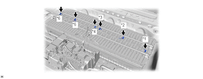
- Visually check the installation condition of the relevant battery temperature sensor.
*1 Battery Temperature Sensor 0 *2 Battery Temperature Sensor 1 *3 Battery Temperature Sensor 2 *4 Battery Temperature Sensor 3 *5 Battery Temperature Sensor 4 *6 Battery Temperature Sensor 5 Standard Condition
Each battery temperature sensor is installed in the correct location with the correct orientation and its claws are engaged securely.
Result
Result Proceed to Each battery temperature sensor is installed in the correct location with the correct orientation and its claws are engaged securely. A Claws are damaged. B Any of battery temperature sensors are not installed correctly, but claws are not damaged. C - Install the upper HV battery cover sub-assembly.
Result:
B
REPLACE HYBRID BATTERY THERMISTOR. Refer to REMOVAL [12/2019 - 10/2022] , or refer to REMOVAL [10/2022 - 11/2023]
Result:
C
INSTALL PARTS CORRECTLY
Result:
A
See step 3
- Check that the service plug grip is not installed.
- CHECK HYBRID BATTERY THERMISTOR (BATTERY TEMPERATURE SENSOR) WARNING:
Be sure to wear insulated gloves.
- Check that the service plug grip is not installed.NOTE:
After removing the service plug grip, do not turn the ignition switch to ON (READY), unless instructed by the repair information because this may cause a malfunction.
- Remove the HV battery junction block assembly.
Refer to REMOVAL [12/2019 - 10/2022] , or refer to REMOVAL [10/2022 - 11/2023]
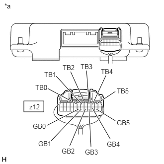
- Disconnect the z12 battery voltage sensor connector.NOTE:
Before disconnecting the connector, check that it is not loose or disconnected.
- Measure the resistance of the circuit for the malfunctioning sensor (battery temperature sensor 0 to 5).
*a Rear view of wire harness connector
(to Battery Voltage Sensor)Tester Connection
Tester Connection Battery Temperature Sensor z12-7 (TB0) - z12-19 (GB0) 0 z12-6 (TB1) - z12-18 (GB1) 1 z12-5 (TB2) - z12-17 (GB2) 2 z12-4 (TB3) - z12-16 (GB3) 3 z12-3 (TB4) - z12-15 (GB4) 4 z12-2 (TB5) - z12-14 (GB5) 5 Standard Resistance
Thermistor Temperature Condition Specified Condition 0 to 10°C (32 to 50°F) Ignition switch off 17.7 to 27.8 kΩ 10 to 20°C (50 to 68°F) Ignition switch off 12.0 to 18.2 kΩ 20 to 30°C (68 to 86°F) Ignition switch off 8.22 to 12.2 kΩ 30 to 40°C (86 to 104°F) Ignition switch off 5.74 to 8.41 kΩ 40 to 50°C (104 to 122°F) Ignition switch off 4.09 to 5.91 kΩ NOTE:When taking a measurement with a tester, do not apply excessive force to the tester probe to avoid damaging the holder.
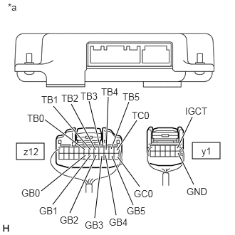
- Disconnect the y1 battery voltage sensor connector.NOTE:
Before disconnecting the connector, check that it is not loose or disconnected.
- Measure the resistance according to the value(s) in the table below.
*a Rear view of wire harness connector
(to Battery Voltage Sensor)Standard Resistance
Tester Connection Condition Specified Condition z12-7 (TB0) - y1-1 (IGCT) Ignition switch off 10 kΩ or higher z12-7 (TB0) - y1-7 (GND) Ignition switch off 10 kΩ or higher z12-19 (GB0) - y1-1 (IGCT) Ignition switch off 10 kΩ or higher z12-19 (GB0) - y1-7 (GND) Ignition switch off 10 kΩ or higher z12-6 (TB1) - y1-1 (IGCT) Ignition switch off 10 kΩ or higher z12-6 (TB1) - y1-7 (GND) Ignition switch off 10 kΩ or higher z12-18 (GB1) - y1-1 (IGCT) Ignition switch off 10 kΩ or higher z12-18 (GB1) - y1-7 (GND) Ignition switch off 10 kΩ or higher z12-5 (TB2) - y1-1 (IGCT) Ignition switch off 10 kΩ or higher z12-5 (TB2) - y1-7 (GND) Ignition switch off 10 kΩ or higher z12-17 (GB2) - y1-1 (IGCT) Ignition switch off 10 kΩ or higher z12-17 (GB2) - y1-7 (GND) Ignition switch off 10 kΩ or higher z12-4 (TB3) - y1-1 (IGCT) Ignition switch off 10 kΩ or higher z12-4 (TB3) - y1-7 (GND) Ignition switch off 10 kΩ or higher z12-16 (GB3) - y1-1 (IGCT) Ignition switch off 10 kΩ or higher z12-16 (GB3) - y1-7 (GND) Ignition switch off 10 kΩ or higher z12-3 (TB4) - y1-1 (IGCT) Ignition switch off 10 kΩ or higher z12-3 (TB4) - y1-7 (GND) Ignition switch off 10 kΩ or higher z12-15 (GB4) - y1-1 (IGCT) Ignition switch off 10 kΩ or higher z12-15 (GB4) - y1-7 (GND) Ignition switch off 10 kΩ or higher z12-2 (TB5) - y1-1 (IGCT) Ignition switch off 10 kΩ or higher z12-2 (TB5) - y1-7 (GND) Ignition switch off 10 kΩ or higher z12-14 (GB5) - y1-1 (IGCT) Ignition switch off 10 kΩ or higher z12-14 (GB5) - y1-7 (GND) Ignition switch off 10 kΩ or higher z12-1 (TC0) - y1-1 (IGCT) Ignition switch off 10 kΩ or higher z12-1 (TC0) - y1-7 (GND) Ignition switch off 10 kΩ or higher z12-13 (GC0) - y1-1 (IGCT) Ignition switch off 10 kΩ or higher z12-13 (GC0) - y1-7 (GND) Ignition switch off 10 kΩ or higher NOTE:When taking a measurement with a tester, do not apply excessive force to the tester probe to avoid damaging the holder.
- Reconnect the y1 and z12 battery voltage sensor connectors.
- Install the HV battery junction block assembly.
Result
Proceed to OK NG
Result:
OK
REPLACE BATTERY VOLTAGE SENSOR. Refer to REMOVAL [12/2019 - 10/2022] , or refer to REMOVAL [10/2022 - 11/2023]
Result:
NG
See step 4
- Check that the service plug grip is not installed.
- CHECK HARNESS AND CONNECTOR (BATTERY TEMPERATURE SENSOR) WARNING:
Be sure to wear insulated gloves and protective goggles.
- Check that the service plug grip is not installed.NOTE:
After removing the service plug grip, do not turn the ignition switch to ON (READY), unless instructed by the repair information because this may cause a malfunction.
- Remove the upper HV battery cover sub-assembly.
Refer to REMOVAL [12/2019 - 10/2022] , or refer to REMOVAL [10/2022 - 11/2023]
- Check the wire harness and connectors of the battery temperature sensor for abnormalities by sight and touch.
Specified Condition
There are no open or short circuits in the wire harness and connectors. There are no short circuits to other wire harnesses.
- Install the upper HV battery cover sub-assembly.
Result
Proceed to OK NG
Result:
OK
REPLACE HYBRID BATTERY THERMISTOR. Refer to REMOVAL [12/2019 - 10/2022] , or refer to REMOVAL [10/2022 - 11/2023]
Result:
NG
REPAIR HARNESS OR CONNECTOR (BATTERY TEMPERATURE SENSOR)
- Check that the service plug grip is not installed.