DTC P0AA0-73: Hybrid/EV Battery Positive and Negative Contactor Actuator Stuck Closed [12/2019 - 11/2023]: Procedure
- CHECK DTC OUTPUT (HYBRID CONTROL, MOTOR GENERATOR)
- Check for DTCs.
Powertrain > Hybrid Control > Trouble Codes
Powertrain > Motor Generator > Trouble Codes
Result
Result Proceed to P0AA0-73 only is output, or DTCs except the ones in the table below are also output. A DTCs of Hybrid Control System in the tables below are output. B DTCs of Motor Generator Control System in the tables below are output. C Malfunction Content System Relevant DTC Microcomputer malfunction Hybrid Control System P0606-47 Hybrid/EV Powertrain Control Module Processor Watchdog / Safety MCU Failure P0606-87 Hybrid/EV Powertrain Control Module Processor to Monitoring Processor Missing Message P060A-47 Hybrid/EV Powertrain Control Module Monitoring Processor Watchdog / Safety MCU Failure P060A-87 Hybrid/EV Powertrain Control Module Processor from Monitoring Processor Missing Message P0A1B-49 Drive Motor "A" Control Module Internal Electronic Failure P1C9E-9F Hybrid/EV System Reset Stuck Off Motor Generator Control System P0A1B-1F Generator Control Module Circuit Intermittent P0A1A-47 Generator Control Module Watchdog / Safety MC Failure P0A1A-49 Generator Control Module Internal Electronic Failure P1C2A-1C Generator A/D Converter Circuit Circuit Voltage Out of Range P1C2A-49 Generator A/D Converter Circuit Internal Electronic Failure P1C2B-1C Drive Motor "A" Control Module A/D Converter Circuit Voltage Out of Range P1C2B-49 Drive Motor "A" Control Module A/D Converter Circuit Internal Electronic Failure P1CAC-49 Generator Position Sensor Internal Electronic Failure P1CAD-49 Drive Motor "A" Position Sensor Internal Electronic Failure P1CAF-38 Generator Position Sensor REF Signal Cycle Malfunction Signal Frequency Incorrect P1CB0-38 Drive Motor "A" Position Sensor REF Signal Frequency Incorrect P3133-83 Communication Error from Generator to Drive Motor "A" Value of Signal Protection Calculation Incorrect P3133-86 Communication Error from Generator to Drive Motor "A" Signal Invalid P3133-87 Communication Error from Generator to Drive Motor "A" Missing Message Power source circuit malfunction Motor Generator Control System P06D6-1C Generator Control Module Offset Power Circuit Voltage Out of Range P06B0-1C Generator Control Module Position Sensor REF Power Source Circuit Voltage Out of Range Communication system malfunction Hybrid Control System P3123-87 Lost Communication with Drive Motor Control Module "A" from Hybrid/EV Control Module Missing Message Sensor and actuator circuit malfunction Hybrid Control System P0AD9-11 Hybrid/EV Battery Positive Contactor Circuit Short to Ground P0AD9-15 Hybrid/EV Battery Positive Contactor Circuit Short to Auxiliary Battery or Open P0ADD-11 Hybrid/EV Battery Negative Contactor Circuit Short to Ground P0ADD-15 Hybrid/EV Battery Negative Contactor Circuit Short to Auxiliary Battery or Open P0AE4-11 Hybrid/EV Battery Precharge Contactor Circuit Short to Ground P0AE4-15 Hybrid/EV Battery Precharge Contactor Circuit Short to Auxiliary Battery or Open Motor Generator Control System P0A3F-16 Drive Motor "A" Position Sensor Circuit Voltage Below Threshold P0A4B-16 Generator Position Sensor Circuit Voltage Below Threshold P0A4B-21 Generator Position Sensor Signal Amplitude < Minimum P0A4B-22 Generator Position Sensor Signal Amplitude > Maximum P0C50-13 Drive Motor "A" Position Sensor Circuit "A" Circuit Open P0C50-16 Drive Motor "A" Position Sensor Circuit "A" Circuit Voltage Below Threshold P0C50-17 Drive Motor "A" Position Sensor Circuit "A" Circuit Voltage Above Threshold P0C5A-13 Drive Motor "A" Position Sensor Circuit "B" Circuit Open P0C5A-16 Drive Motor "A" Position Sensor Circuit "B" Circuit Voltage Below Threshold P0C5A-17 Drive Motor "A" Position Sensor Circuit "B" Circuit Voltage Above Threshold P0C64-13 Generator Position Sensor Circuit "A" Circuit Open P0C64-16 Generator Position Sensor Circuit "A" Circuit Voltage Below Threshold P0C64-17 Generator Position Sensor Circuit "A" Circuit Voltage Above Threshold P0C69-13 Generator Position Sensor Circuit "B" Circuit Open P0C69-16 Generator Position Sensor Circuit "B" Circuit Voltage Below Threshold P0C69-17 Generator Position Sensor Circuit "B" Circuit Voltage Above Threshold System malfunction Hybrid Control System P0C76-00 Hybrid/EV Battery System Discharge Time Too Long P0D2D-1C Drive Motor "A" Inverter Voltage Sensor Voltage Out of Range P1C83-49 High Voltage Power Resource Circuit Voltage Sensor after Boosting Malfunction Motor Generator Control System P0D2D-16 Drive Motor "A" Inverter Voltage Sensor (VH) Circuit Voltage Below Threshold P0D2D-17 Drive Motor "A" Inverter Voltage Sensor (VH) Circuit Voltage Above Threshold P1CB6-9E Drive Motor "A" Inverter Voltage Sensor (VH) Stuck On HINT:
- P0AA0-73 may be output as a result of the malfunction indicated by the DTCs above.
- The chart above is listed in inspection order of priority.
- Check DTCs that are output at the same time by following the listed order. (The main cause of the malfunction can be determined without performing unnecessary inspections.)
- P0AA0-73 may be output as a result of the malfunction indicated by the DTCs above.
- Turn the ignition switch off.
Result:
B
GO TO DTC CHART (HYBRID CONTROL SYSTEM)
Refer to DIAGNOSTIC TROUBLE CODE CHART [12/2019 - 09/2020] , or refer to DIAGNOSTIC TROUBLE CODE CHART [09/2020 - 10/2021] , or refer to DIAGNOSTIC TROUBLE CODE CHART [10/2021 - 11/2023]
Result:
C
GO TO DTC CHART (MOTOR GENERATOR CONTROL SYSTEM) . Refer to DIAGNOSTIC TROUBLE CODE CHART [12/2019 - 10/2021] , or refer to DIAGNOSTIC TROUBLE CODE CHART [10/2021 - 11/2023]
Result:
A
See step 2
- Check for DTCs.
- CHECK FREEZE FRAME DATA (HYBRID CONTROL)
- Read the Freeze Frame Data of DTC P0AA0-73.
Powertrain > Hybrid Control > Trouble Codes
NOTE:As freeze frame data is stored immediately before and after a DTC is stored, make sure to only read the values for the moment the DTC was stored ("0(s)").
Result
Result Proceed to Difference between "VL-Voltage before Boosting" and "VH-Voltage after Boosting" is less than 76 V. A Difference between "VL-Voltage before Boosting" and "VH-Voltage after Boosting" is 76 V or more. B HINT:
If VH-Voltage after Boosting is output even when an off command is being sent to the system main relay (positive side), P0AA0-73 is output. If the difference between the "VL-Voltage before Boosting" and the "VH-Voltage after Boosting" is large, it is determined that there is an inverter (VH sensor) malfunction.
- Turn the ignition switch off.
Result:
B
REPLACE INVERTER WITH CONVERTER ASSEMBLY
Refer to REMOVAL [12/2019 - 10/2022] , or refer to REMOVAL [10/2022 - 11/2023]
Result:
A
See step 3
- Read the Freeze Frame Data of DTC P0AA0-73.
- CHECK CONNECTOR CONNECTION CONDITION (HYBRID VEHICLE CONTROL ECU CONNECTOR)
Refer to PROCEDURE - Step 1
Result
Proceed to OK NG Result:
OK
See step 5
Result:
NG
See step 4
- CONNECT SECURELY
Result
Proceed to NEXT Result:
NEXT
See step 5
- CHECK CONNECTOR CONNECTION CONDITION (FLOOR WIRE CONNECTOR)
See step 5
Result
Result Proceed to OK A NG (The connector is not connected securely.) B NG (The terminals are not making secure contact or are deformed, or water or foreign matter exists in the connector.) C Result:
A
See step 8
Result:
C
See step 7
Result:
B
See step 6
- CONNECT SECURELY
Result
Proceed to NEXT Result:
NEXT
See step 8
- REPAIR OR REPLACE HARNESS OR CONNECTOR
Result
Proceed to NEXT Result:
NEXT
See step 8
- CHECK CONNECTOR CONNECTION CONDITION (HV BATTERY JUNCTION BLOCK ASSEMBLY CONNECTOR) WARNING:
Be sure to wear insulated gloves.
- Check that the service plug grip is not installed.NOTE:
After removing the service plug grip, do not turn the ignition switch to ON, unless instructed by the repair information because this may cause a malfunction.
- Remove the No. 10 HV battery shield panel.
Refer to REMOVAL [12/2019 - 10/2022] , or refer to REMOVAL [10/2022 - 11/2023]
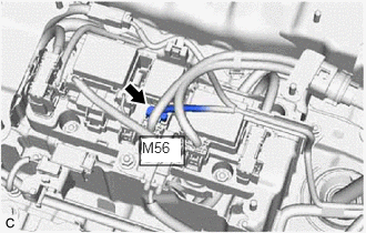
- Check the connector connections and contact pressure of the relevant terminals of the M56 HV battery junction block assembly connector.
Refer to ELECTRONIC CIRCUIT INSPECTION PROCEDURE [12/2019 - ]
OK
The connectors are connected securely and there are no contact pressure problems.
- Install the No. 10 HV battery shield panel.
Result
Proceed to OK NG
Result:
OK
See step 10
Result:
NG
See step 9
- Check that the service plug grip is not installed.
- CONNECT SECURELY
Result
Proceed to NEXT Result:
NEXT
See step 10
- CHECK GROUND WIRE CONNECTION CONDITION (SMR ACTIVATION LOW-VOLTAGE CIRCUIT)
See step 10
Result
Proceed to OK NG Result:
OK
See step 12
Result:
NG
See step 11
- CONNECT SECURELY
Result
Proceed to NEXT Result:
NEXT
See step 12
- CHECK HARNESS AND CONNECTOR (HYBRID VEHICLE CONTROL ECU - HV BATTERY JUNCTION BLOCK ASSEMBLY) WARNING:
Be sure to wear insulated gloves.
- Check that the service plug grip is not installed.NOTE:
After removing the service plug grip, do not turn the ignition switch to ON, unless instructed by the repair information because this may cause a malfunction.
- Remove the No. 10 HV battery shield panel.
Refer to REMOVAL [12/2019 - 10/2022] , or refer to REMOVAL [10/2022 - 11/2023]
- Disconnect the M56 HV battery junction block assembly connector.
- Disconnect the A32 hybrid vehicle control ECU connector.
- Measure the resistance according to the value(s) in the table below.
Standard Resistance (Check for Open)
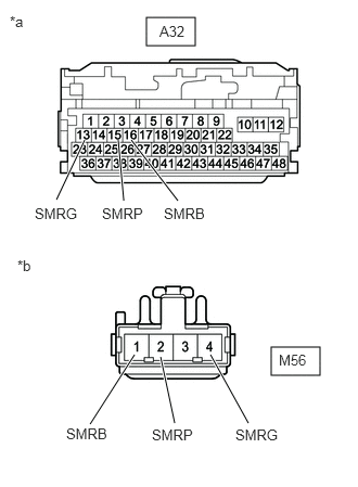
Tester Connection Condition Specified Condition A32-16 (SMRB) - M56-1 (SMRB) Ignition switch off Below 1 Ω A32-13 (SMRG) - M56-4 (SMRG) Ignition switch off Below 1 Ω A32-15 (SMRP) - M56-2 (SMRP) Ignition switch off Below 1 Ω Standard Resistance (Check for Short)
Tester Connection Condition Specified Condition A32-16 (SMRB) or M56-1 (SMRB) - Body ground and other terminals Ignition switch off 10 kΩ or higher A32-13 (SMRG) or M56-4 (SMRG) - Body ground and other terminals Ignition switch off 10 kΩ or higher A32-15 (SMRP) or M56-2 (SMRP) - Body ground and other terminals Ignition switch off 10 kΩ or higher *a Front view of wire harness connector
(to Hybrid Vehicle Control ECU)*b Front view of wire harness connector
(to HV Battery Junction Block Assembly) - Reconnect the A32 hybrid vehicle control ECU connector.
- Reconnect the M56 HV battery junction block assembly connector.
- Install the No. 10 HV battery shield panel.
Result
Proceed to OK NG
Result:
OK
See step 14
Result:
NG
See step 13
- Check that the service plug grip is not installed.
- REPAIR OR REPLACE HARNESS OR CONNECTOR
Result
Proceed to NEXT Result:
NEXT
See step 14
- CHECK HARNESS AND CONNECTOR (HV BATTERY JUNCTION BLOCK ASSEMBLY - BODY GROUND) WARNING:
Be sure to wear insulated gloves.
- Check that the service plug grip is not installed.NOTE:
After removing the service plug grip, do not turn the ignition switch to ON, unless instructed by the repair information because this may cause a malfunction.
- Remove the No. 10 HV battery shield panel.
Refer to REMOVAL [12/2019 - 10/2022] , or refer to REMOVAL [10/2022 - 11/2023]
- Disconnect the M56 HV battery junction block assembly connector.
- Measure the resistance according to the value(s) in the table below.
Standard Resistance
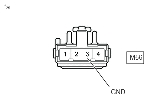
Tester Connection Condition Specified Condition M56-3 (GND) - Body ground Ignition switch off Below 1 Ω *a Front view of wire harness connector
(to HV Battery Junction Block Assembly) - Reconnect the M56 HV battery junction block assembly connector.
- Install the No. 10 HV battery shield panel.
Result
Proceed to OK NG
Result:
OK
See step 16
Result:
NG
See step 15
- Check that the service plug grip is not installed.
- REPAIR OR REPLACE HARNESS OR CONNECTOR
Result
Proceed to NEXT Result:
NEXT
See step 16
- INSPECT HV BATTERY JUNCTION BLOCK ASSEMBLY (SMRB, SMRG, SMRP) WARNING:
Be sure to wear insulated gloves.
- Check that the service plug grip is not installed.NOTE:
After removing the service plug grip, do not turn the ignition switch to ON, unless instructed by the repair information because this may cause a malfunction.
- Remove the No. 10 HV battery shield panel.
Refer to REMOVAL [12/2019 - 10/2022] , or refer to REMOVAL [10/2022 - 11/2023]
- Disconnect the M56 HV battery junction block assembly connector.
- Measure the resistance according to the value(s) in the table below.
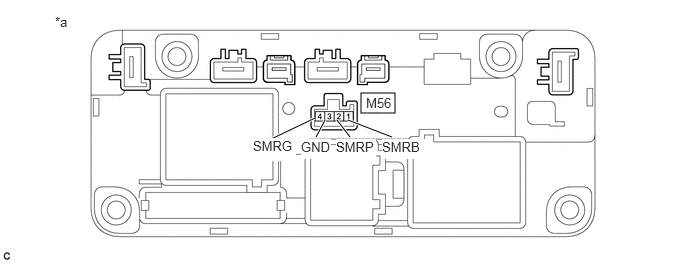
*a Component without harness connected
(HV Battery Junction Block Assembly)- - Standard Resistance
Tester Connection Condition Specified Condition M56-1 (SMRB) - M56-3 (GND) -40 to 80°C (-40 to 176°F) 25.0 to 59.0 Ω M56-4 (SMRG) - M56-3 (GND) -40 to 80°C (-40 to 176°F) 25.0 to 59.0 Ω M56-2 (SMRP) - M56-3 (GND) -40 to 80°C (-40 to 176°F) 140 to 290 Ω - Reconnect the M56 HV battery junction block assembly connector.
- Install the No. 10 HV battery shield panel.
Result
Proceed to OK NG
Result:
NG
See step 19
Result:
OK
See step 17
- Check that the service plug grip is not installed.
- CHECK HV BATTERY JUNCTION BLOCK ASSEMBLY (SMRB, SMRG, SMRP) WARNING:
Be sure to wear insulated gloves.
- Check that the service plug grip is not installed.NOTE:
After removing the service plug grip, do not turn the ignition switch to ON, unless instructed by the repair information because this may cause a malfunction.
- Remove the No. 10 HV battery shield panel.
Refer to REMOVAL [12/2019 - 10/2022] , or refer to REMOVAL [10/2022 - 11/2023]
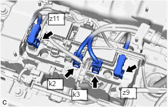
- Disconnect the 2 HV floor under wire connectors from the HV battery junction block assembly.
- Disconnect the 2 HV battery high voltage connectors from the HV battery junction block assembly.NOTE:
Insulate each disconnected high-voltage connector with insulating tape. Wrap the connector from the wire harness side to the end of the connector.
- Measure the resistance according to the value(s) in the table below.
Standard Resistance
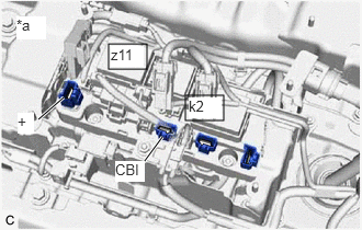
Tester Connection Condition Specified Condition k2-1 (CBI) - z11-1 (+) Ignition switch off 10 kΩ or higher HINT:
- If a system main relay is stuck closed, inspect the HV battery junction block assembly without removing it from the vehicle, in order to keep the relay closed.
- If the result of reading the freeze frame data is A, the HV battery junction block assembly must be replaced. Measuring resistance can determine that this is either a present or past malfunction.
*a Component without harness connected
(HV Battery Junction Block Assembly) - Measure the resistance according to the value(s) in the table below.
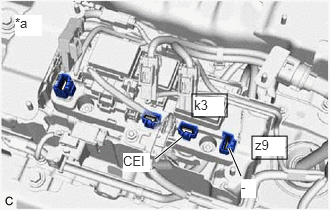
Standard Resistance
Tester Connection Condition Specified Condition k3-1 (CEI) - z9-1 (-) Ignition switch off 10 kΩ or higher HINT:
- If a system main relay is stuck closed, inspect the HV battery junction block assembly without removing it from the vehicle, in order to keep the relay closed.
- If the result of reading the freeze frame data is A, the HV battery junction block assembly must be replaced. Measuring resistance can determine that this is either a present or past malfunction.
- If the resistance is between 24.3 and 29.7 Ω, it can be determined that SMRP is stuck closed.
*a Component without harness connected
(HV Battery Junction Block Assembly) - Reconnect the 2 HV battery high voltage connectors.
- Reconnect the 2 HV floor under wire connectors.
- Install the No. 10 HV battery shield panel.
Result
Result Judgment Proceed to OK Past malfunction A NG Present malfunction B
Result:
B
See step 20
Result:
A
See step 18
- Check that the service plug grip is not installed.
- REPLACE HV BATTERY JUNCTION BLOCK ASSEMBLY
Refer to REMOVAL [12/2019 - 10/2022] , or refer to REMOVAL [10/2022 - 11/2023]
Result
Proceed to NEXT Result:
NEXT
See step 21
- REPLACE HV BATTERY JUNCTION BLOCK ASSEMBLY
Refer to REMOVAL [12/2019 - 10/2022] , or refer to REMOVAL [10/2022 - 11/2023]
Result
Proceed to NEXT Result:
NEXT
See step 21
- REPLACE HV BATTERY JUNCTION BLOCK ASSEMBLY
Refer to REMOVAL [12/2019 - 10/2022] , or refer to REMOVAL [10/2022 - 11/2023]
Result
Proceed to NEXT Result:
NEXT
See step 21
- CHECK HYBRID VEHICLE CONTROL ECU (CHECK FOR NORMAL OPERATION)
See step 21
Result
Result Proceed to Difference between "Hybrid Battery Voltage" and "VL-Voltage before Boosting" is always less than 100 V. A Difference between "Hybrid Battery Voltage" and "VL-Voltage before Boosting" is 100 V or more. B Result:
A
END
Result:
B
REPLACE HYBRID VEHICLE CONTROL ECU AND HV BATTERY JUNCTION BLOCK ASSEMBLY
HYBRID VEHICLE CONTROL ECU: Refer to REMOVAL [12/2019 - 10/2022] , or refer to REMOVAL [10/2022 - 11/2023]
HV BATTERY JUNCTION BLOCK ASSEMBLY: Refer to REMOVAL [12/2019 - 10/2022] , or refer to REMOVAL [10/2022 - 11/2023]