Installation [11/2023 - ]: Procedure
- TEMPORARILY INSTALL FUEL (ENGINE ROOM SIDE) PUMP ASSEMBLY NOTE:
When replacing the fuel pump assembly, it is necessary to replace the No. 1 fuel pipe sub-assembly with a new one.
HINT:
Perform "Inspection After Repair" after replacing the fuel pump assembly.
Refer to INITIALIZATION [10/2021 - ]
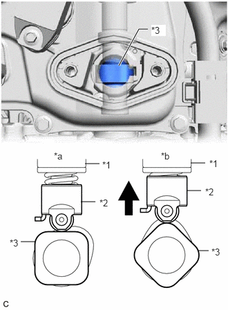
- Turn the crankshaft pulley until the flat of the No. 2 camshaft faces the fuel pump lifter assembly.
*1 Fuel Pump Assembly *2 Fuel Pump Lifter Assembly *3 No. 2 Camshaft *a Correct *b Incorrect HINT:
This prevents the No. 2 camshaft nose from pushing up the fuel pump lifter assembly when installing the fuel pump assembly.
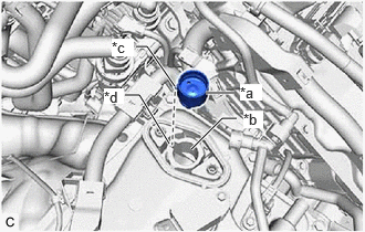
- Apply 30 cc (1.8 cu. in.) of engine oil to the pump drive cam.
*1 Fuel Pump Spacer Gasket *a Pump Drive Cam (Engine Oil Application Area) *b Fuel Pump Lifter Assembly (Engine Oil Application Area) - Apply engine oil to the fuel pump lifter assembly.
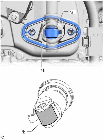
- Install a new fuel pump spacer gasket to the cylinder head cover sub-assembly and No. 4 camshaft bearing cap.
- Apply engine oil to the inside of the fuel pump lifter guide and the outside of the fuel pump lifter assembly.
*a Fuel Pump Lifter Assembly (Engine Oil Application Area) *b Fuel Pump Lifter Guide (Engine Oil Application Area) *c Stopper Key *d Key Groove - Set the fuel pump lifter assembly on the fuel pump lifter guide as shown in the illustration.
HINT:
Align the stopper key of the fuel pump lifter assembly with the key groove of the fuel pump lifter guide.
- Apply engine oil to a new O-ring and install it to the fuel pump assembly.NOTE:
Do not damage the O-ring.
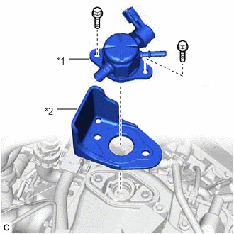
- Set the fuel pump flange and fuel pump assembly on the No. 4 camshaft bearing cap as shown in the illustration.
*1 Fuel Pump Assembly *2 Fuel Pump Flange - Temporarily install the fuel pump assembly with the 2 bolts, leaving some allowance for left and right movement.
- Turn the crankshaft pulley until the flat of the No. 2 camshaft faces the fuel pump lifter assembly.
- TEMPORARILY INSTALL NO. 1 FUEL PIPE SUB-ASSEMBLY NOTE:
Do not damage the seals of the union nuts of the No. 1 fuel pipe sub-assembly.
- Temporarily install the bolt.
- Temporarily install the No. 1 fuel pipe sub-assembly to the fuel delivery pipe and tighten the union nut by hand.
- Temporarily install the No. 1 fuel pipe sub-assembly to the fuel pump assembly and tighten the union nut by hand.
- INSTALL FUEL (ENGINE ROOM SIDE) PUMP ASSEMBLY
- Tighten the 2 bolts.
Torque: 28.5 N.m (291 kgf/cm, 21 ft.lbf)
- Connect the fuel pump assembly connector.
- Tighten the 2 bolts.
- INSTALL NO. 1 FUEL PIPE SUB-ASSEMBLY
- for EGR Valve Bracket Connection Type:
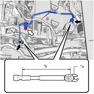
- Using a 17 mm union nut wrench, tighten the union nut on the fuel delivery pipe side of the No. 1 fuel pipe sub-assembly.
*a 17 mm Union Nut Wrench *b Torque Wrench Fulcrum Length 
Union Nut 
Bolt Specified tightening torque
Torque: 35 N.m (357 kgf/cm, 26 ft.lbf)
NOTE:Do not adjust the torque in the loosening direction.
HINT:
- Calculate the torque wrench reading when changing the fulcrum length of the torque wrench.
Refer to PRECAUTION [11/2023 - ]
- When using a 17 mm union nut wrench (fulcrum length of 30 mm (1.18 in.)) + torque wrench (fulcrum length of 180 mm (7.09 in.)): 30 N.m (306 kgf/cm, 22 ft.lbf)
- Calculate the torque wrench reading when changing the fulcrum length of the torque wrench.
- Using a 17 mm union nut wrench, tighten the union nut on the fuel pump assembly side of the No. 1 fuel pipe sub-assembly.
Specified tightening torque
Torque: 35 N.m (357 kgf/cm, 26 ft.lbf)
NOTE:Do not adjust the torque in the loosening direction.
HINT:
- Calculate the torque wrench reading when changing the fulcrum length of the torque wrench.
Refer to PRECAUTION [11/2023 - ]
- When using a 17 mm union nut wrench (fulcrum length of 30 mm (1.18 in.)) + torque wrench (fulcrum length of 180 mm (7.09 in.)): 30 N.m (306 kgf/cm, 22 ft.lbf)
- Calculate the torque wrench reading when changing the fulcrum length of the torque wrench.
- Using an 8 mm socket wrench, tighten the bolt.
Torque: 10 N.m (102 kgf/cm, 7 ft.lbf)
- Using a 17 mm union nut wrench, tighten the union nut on the fuel delivery pipe side of the No. 1 fuel pipe sub-assembly.
- for Cylinder Head Cover Sub-assembly Connection Type:
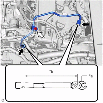
- Using a 17 mm union nut wrench, tighten the union nut on the fuel delivery pipe side of the No. 1 fuel pipe sub-assembly.
*a 17 mm Union Nut Wrench *b Torque Wrench Fulcrum Length Union Nut Bolt Specified tightening torque
Torque: 35 N.m (357 kgf/cm, 26 ft.lbf)
NOTE:Do not adjust the torque in the loosening direction.
HINT:
- Calculate the torque wrench reading when changing the fulcrum length of the torque wrench.
Refer to PRECAUTION [11/2023 - ]
- When using a 17 mm union nut wrench (fulcrum length of 30 mm (1.18 in.)) + torque wrench (fulcrum length of 180 mm (7.09 in.)): 30 N.m (306 kgf/cm, 22 ft.lbf)
- Calculate the torque wrench reading when changing the fulcrum length of the torque wrench.
- Using a 17 mm union nut wrench, tighten the union nut on the fuel pump assembly side of the No. 1 fuel pipe sub-assembly.
Specified tightening torque
Torque: 35 N.m (357 kgf/cm, 26 ft.lbf)
NOTE:Do not adjust the torque in the loosening direction.
HINT:
- Calculate the torque wrench reading when changing the fulcrum length of the torque wrench.
Refer to PRECAUTION [11/2023 - ]
- When using a 17 mm union nut wrench (fulcrum length of 30 mm (1.18 in.)) + torque wrench (fulcrum length of 180 mm (7.09 in.)): 30 N.m (306 kgf/cm, 22 ft.lbf)
- Calculate the torque wrench reading when changing the fulcrum length of the torque wrench.
- Using an 8 mm socket wrench, tighten the bolt.
Torque: 10 N.m (102 kgf/cm, 7 ft.lbf)
- Using a 17 mm union nut wrench, tighten the union nut on the fuel delivery pipe side of the No. 1 fuel pipe sub-assembly.
- Connect the ignition coil connector.
- for EGR Valve Bracket Connection Type:
- INSTALL NO. 2 WATER BY-PASS PIPE
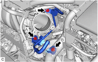
- Temporarily install the No. 2 water by-pass pipe to the cylinder block sub-assembly with the bolt (B).
- Using an 8 mm socket wrench, temporarily install the No. 2 water by-pass pipe to the intake manifold with the 2 bolts (A).
- Tighten the bolt (B).
Torque: 21 N.m (214 kgf/cm, 15 ft.lbf)
- Using an 8 mm socket wrench, tighten the 2 bolts (A).
Torque: 10 N.m (102 kgf/cm, 7 ft.lbf)
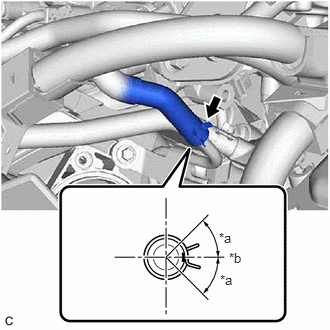
- Connect the No. 8 water by-pass hose to the No. 2 water by-pass pipe and slide the clip to secure it.
HINT:
Engage the clip within the area shown in the illustration.
*a 45° *b Left Side of Vehicle - Engage the clamp to connect the HV air conditioning wire.
- Temporarily install the No. 2 water by-pass pipe to the cylinder block sub-assembly with the bolt (B).
- CONNECT FUEL TUBE SUB-ASSEMBLY
- Connect the fuel tube sub-assembly to the fuel pump assembly and fuel delivery pipe sub-assembly.
Refer to PRECAUTION [11/2023 - ]
- Install the fuel pipe clamp to the fuel tube connector.
- Connect the fuel tube sub-assembly to the fuel pump assembly and fuel delivery pipe sub-assembly.
- INSTALL THROTTLE BODY WITH MOTOR ASSEMBLY
Refer to INSTALLATION [09/2020 - ]
- CONNECT CABLE TO NEGATIVE AUXILIARY BATTERY TERMINAL
Refer to PROCEDURE - Step 2
- INSTALL BATTERY SERVICE HOLE COVER
Refer to PROCEDURE - Step 66
- INSPECT FOR FUEL LEAK
Refer to PROCEDURE - Step 1
- PERFORM INITIALIZATION
- Perform "Inspection After Repair" after replacing the fuel pump assembly.
Refer to INITIALIZATION [10/2021 - ]
- Perform "Inspection After Repair" after replacing the fuel pump assembly.
- INITIALIZATION AFTER RECONNECTING AUXILIARY BATTERY TERMINAL
HINT:
When disconnecting and reconnecting the auxiliary battery, there is an automatic learning function that completes learning when the respective system is used.