Installation [10/2021 - ]: Procedure
WARNING: This page is about a different variant/trim than selected.
- INSTALL EGR COOLER ASSEMBLY
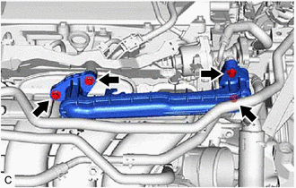
- Using an 8 mm socket wrench, loosen the 4 bolts of the No. 1 EGR pipe sub-assembly.
HINT:
- As the bolts of the No. 1 EGR pipe sub-assembly are only to be loosened, it is not necessary to replace the EGR inlet gasket and EGR valve adapter gasket.
- If the No. 1 EGR pipe sub-assembly is removed, it is necessary to replace the EGR inlet gasket and EGR valve adapter gasket with new ones.
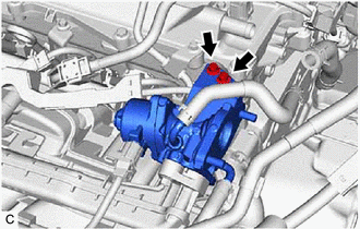
- Using an 8 mm socket wrench, loosen the 2 bolts of the EGR valve assembly.
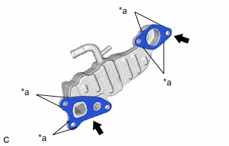
- Install a new EGR cooler gasket to the EGR cooler assembly.NOTE:
Make sure that the claws of the EGR cooler gasket are toward the EGR cooler assembly side.
*a Claw - Install a new EGR valve gasket to the EGR cooler assembly.NOTE:
Make sure that the claws of the EGR valve gasket are toward the EGR cooler assembly side.
- Type A:
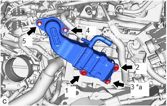 Courtesy of © TOYOTA, LICENSE AGREEMENT TMS1002
*a Bolt or Nut - Temporarily install the EGR cooler assembly to the cylinder head sub-assembly and EGR valve assembly with the 3 bolts and 2 nuts.
- Tighten the 3 bolts and 2 nuts in the order shown in the illustration.
Torque: 24 N.m (245 kgf/cm, 18 ft.lbf)
- Type B:
- Temporarily install the EGR cooler assembly to the cylinder head sub-assembly and EGR valve assembly with the 2 bolts and 3 nuts.
- Tighten the 2 bolts and 3 nuts in the order shown in the illustration.
Torque: 24 N.m (245 kgf/cm, 18 ft.lbf)
- Connect the No. 3 water by-pass hose and No. 4 water by-pass hose to the EGR cooler assembly and slide the 2 clips to secure them.
- Using an 8 mm socket wrench, tighten the 2 bolts of the EGR valve assembly.
Torque: 10 N.m (102 kgf/cm, 7 ft.lbf)
- Using an 8 mm socket wrench, tighten the 4 bolts of the No. 1 EGR pipe sub-assembly.
Torque: 10 N.m (102 kgf/cm, 7 ft.lbf)
- Using an 8 mm socket wrench, loosen the 4 bolts of the No. 1 EGR pipe sub-assembly.
- INSTALL INVERTER WITH CONVERTER ASSEMBLY
Refer to INSTALLATION [12/2019 - 11/2023] , or refer to INSTALLATION [11/2023 - ]
- ADD ENGINE COOLANT (for Engine)
Refer to PROCEDURE - Step 2
- INSPECT FOR COOLANT LEAK (for Engine)
Refer to PROCEDURE - Step 1
- INSPECT FOR EXHAUST GAS LEAK
Refer to PROCEDURE - Step 6 [12/2019 - 10/2022] , or refer to PROCEDURE - Step 6 [10/2022 - ]