Installation [12/2019 - ]: Procedure
WARNING: This page is about a different variant/trim than selected.
- INSTALL FLOW SHUTTING VALVE (WATER BY-PASS HOSE ASSEMBLY)
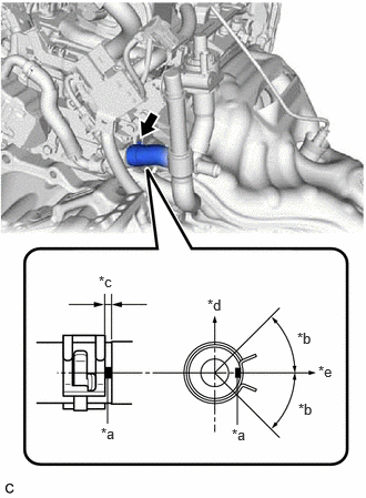
- Connect the flow shutting valve (water by-pass hose assembly) to the water by-pass outlet sub-assembly and slide the clip to secure it.
*a Paint Mark *b 45° (Tabs of Clip Installation Area) *c 2 to 7 mm (0.0787 to 0.276 in.) *d Upper Side of Vehicle *e Right Side of Vehicle NOTE:- Make sure to slide the flow shutting valve (water by-pass hose assembly) until it contacts the hose stopper of the water by-pass outlet sub-assembly.
- Make sure that the tabs of the clip are within the area shown in the illustration.
- Install the wire harness clamp bracket with the bolt.
Torque: 13 N.m (133 kgf/cm, 10 ft.lbf)
- Engage the 2 wire harness clamps.
- Connect the flow shutting valve (water by-pass hose assembly) with the bolt.
Torque: 19 N.m (194 kgf/cm, 14 ft.lbf)
- Connect the No. 2 water by-pass pipe sub-assembly with the bolt.
Torque: 19 N.m (194 kgf/cm, 14 ft.lbf)
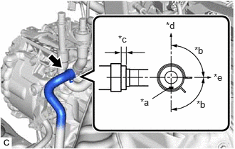
- Connect the heater water hose to the flow shutting valve (water by-pass hose assembly) and slide the clip to secure it.
*a Paint Mark *b 90° (Tabs of Clip Installation Area) *c 2 to 7 mm (0.0787 to 0.276 in.) *d Upper Side of Vehicle *e Right Side of Vehicle NOTE:- Make sure to slide the heater water hose until it contacts the hose stopper of the flow shutting valve (water by-pass hose assembly).
- Make sure that the tabs of the clip are within the area shown in the illustration.
- Connect the inlet heater water hose B connector to the flow shutting valve (water by-pass hose assembly).NOTE:
Check that there is no damage or foreign matter on the connecting parts of the water lines.
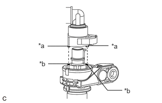
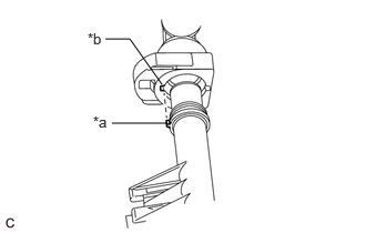
- Align the protrusions of the inlet heater water hose B connector with the cutouts in the flow shutting valve (water by-pass hose assembly) and securely insert the inlet heater water hose B connector to the stopper of the pipe.
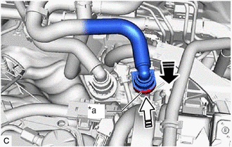
*a Protrusion *b Cutout - Push in the retainer.
*a Retainer 
Push 
Push in - Check that the flow shutting valve (water by-pass hose assembly) and inlet heater water hose B connector are securely connected by pulling on them.
- Align the protrusions of the inlet heater water hose B connector with the cutouts in the flow shutting valve (water by-pass hose assembly) and securely insert the inlet heater water hose B connector to the stopper of the pipe.
- Connect the outlet heater water hose B connector to the No. 2 water by-pass pipe sub-assembly.NOTE:
Check that there is no damage or foreign matter on the connecting parts of the water lines.
- Align the protrusion of the No. 2 water by-pass pipe sub-assembly with the cutout in the outlet heater water hose B connector and securely insert the outlet heater water hose B connector to the stopper of the pipe.
*a Protrusion *b Cutout - Push in the retainer.
*a Retainer Push Push in - Check that the No. 2 water by-pass pipe sub-assembly and outlet heater water hose B connector are securely connected by pulling on them.
- Align the protrusion of the No. 2 water by-pass pipe sub-assembly with the cutout in the outlet heater water hose B connector and securely insert the outlet heater water hose B connector to the stopper of the pipe.
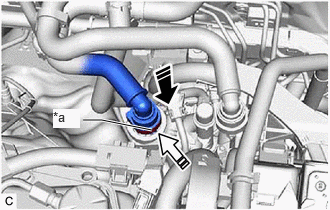
- Connect the flow shutting valve (water by-pass hose assembly) connector.
- Connect the flow shutting valve (water by-pass hose assembly) to the water by-pass outlet sub-assembly and slide the clip to secure it.
- INSTALL INVERTER WITH CONVERTER ASSEMBLY
Refer to INSTALLATION [12/2019 - 11/2023] , or refer to INSTALLATION [11/2023 - ]
- ADD ENGINE COOLANT (for Engine)
Refer to PROCEDURE - Step 2
- INSPECT FOR COOLANT LEAK (for Engine)
Refer to PROCEDURE - Step 1