On-Vehicle Inspection [11/2023 - ]: Procedure
- DISABLE BRAKE CONTROL (for HV Model)
Refer to PROCEDURE - Step 1
- REMOVE FRONT WHEEL
Refer to PROCEDURE - Step 1
- SEPARATE FRONT FLEXIBLE HOSE
See step 3
- SEPARATE FRONT DISC BRAKE CALIPER ASSEMBLY
See step 4
- REMOVE FRONT DISC
Refer to PROCEDURE - Step 12
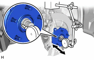
- INSPECT FRONT AXLE HUB BEARING LOOSENESS
- Using a dial indicator with magnetic base, check for looseness near the center of the front axle hub sub-assembly.
Maximum Looseness
0.05 mm (0.00196 in.)
NOTE:- Ensure that the dial indicator is set perpendicular to the measurement surface.
- Keep the magnet of the dial indicator away from the front axle hub sub-assembly and front speed sensor.
HINT:
If the looseness exceeds the maximum, replace the front axle hub sub-assembly.
- Using a dial indicator with magnetic base, check for looseness near the center of the front axle hub sub-assembly.
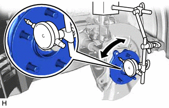
- INSPECT FRONT AXLE HUB RUNOUT
- Using a dial indicator with magnetic base, check for runout on the surface of the front axle hub sub-assembly outside the front axle hub bolts.
Maximum Runout
0.05 mm (0.00196 in.)
NOTE:- Ensure that the dial indicator is set perpendicular to the measurement surface.
- Make sure to set the tip of the dial indicator towards the outside of the front axle hub bolts.
- Keep the magnet of the dial indicator away from the front axle hub sub-assembly and front speed sensor.
HINT:
If the runout exceeds the maximum, replace the front axle hub sub-assembly.
- Using a dial indicator with magnetic base, check for runout on the surface of the front axle hub sub-assembly outside the front axle hub bolts.
- INSTALL FRONT DISC
Refer to PROCEDURE - Step 1
- INSTALL FRONT DISC BRAKE CALIPER ASSEMBLY
See step 9
- INSTALL FRONT FLEXIBLE HOSE
See step 10
- INSTALL FRONT WHEEL
Refer to PROCEDURE - Step 1
- CONNECT CABLE TO NEGATIVE AUXILIARY BATTERY TERMINAL (for HV Model)
- Connect the reservoir level switch connector.
- Install the brake master cylinder reservoir assembly to the reservoir bracket with the bolt and nut.
Torque: 9.0 N.m (92 kgf/cm, 80 in.lbf)
- Engage the clamp to install the wire harness to the brake master cylinder reservoir assembly.
- Connect the cable to the negative (-) auxiliary battery terminal.
Refer to PROCEDURE - Step 2
- Turn the ignition switch to ON (READY).
- Depress the brake pedal and release it.
- Clear the DTCs.
Refer to DTC CHECK / CLEAR [12/2019 - ]