Removal [10/2022 - 11/2023]: Procedure
- DISABLE BRAKE CONTROL (for HV Model)
Refer to PROCEDURE - Step 4
- REMOVE REAR WHEEL
Refer to PROCEDURE - Step 1
- REMOVE REAR SUSPENSION ARM COVER
Refer to PROCEDURE - Step 3
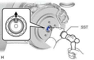
- REMOVE REAR AXLE SHAFT NUT
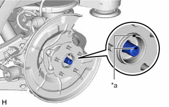
- Using SST and a hammer, release the staked part of the rear axle shaft nut.
- SST: 09930-00010
NOTE:Loosen the staked part of the rear axle shaft nut completely, otherwise the threads of the rear drive shaft assembly may be damaged.
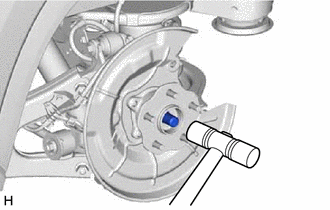
- While applying the brakes, using a 30 mm deep socket wrench, remove the rear axle shaft nut.
- Using SST and a hammer, release the staked part of the rear axle shaft nut.
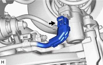
- DISCONNECT NO. 2 PARKING BRAKE WIRE ASSEMBLY
- Disconnect the No. 2 parking brake wire assembly connector from the parking brake actuator assembly.NOTE:
- Remove any dirt or foreign matter on and around the No. 2 parking brake wire assembly connector before performing this step.
- Do not allow water, oil or dirt to enter the No. 2 parking brake wire assembly connector.
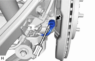
- Using a screwdriver with its tip wrapped with protective tape, disconnect the No. 2 parking brake wire assembly connector from the rear skid control sensor.
*a Protective Tape NOTE:- Remove any dirt or foreign matter on and around the No. 2 parking brake wire assembly connector before performing this step.
- Do not allow water, oil or dirt to enter the No. 2 parking brake wire assembly connector.
- Be careful not to damage the rear skid control sensor or connector cover.
- Disconnect the No. 2 parking brake wire assembly connector from the parking brake actuator assembly.
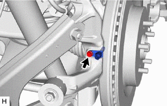
- REMOVE REAR SKID CONTROL SENSOR
- Remove the bolt and the rear skid control sensor from the rear axle carrier sub-assembly.NOTE:
- Keep the tip of the rear skid control sensor and installation hole free of foreign matter.
- Do not rotate or apply excessive force to the rear skid control sensor when removing it from the rear axle carrier sub-assembly. Rotating or applying excessive force may result in damage to the rear skid control sensor.
- Remove the bolt and the rear skid control sensor from the rear axle carrier sub-assembly.
- SEPARATE REAR DISC BRAKE CYLINDER ASSEMBLY
See step 4
- REMOVE REAR DISC BRAKE CYLINDER MOUNTING WITH BRAKE PAD
See step 5
- REMOVE REAR DISC
Refer to PROCEDURE - Step 16
- REMOVE REAR AXLE HUB AND BEARING ASSEMBLY
- Put matchmarks on the rear drive shaft assembly and rear axle hub and bearing assembly.
*a Matchmark - Using a plastic hammer, separate the rear drive shaft assembly from the rear axle hub and bearing assembly.
HINT:
If it is difficult to separate the rear drive shaft assembly from the rear axle hub and bearing assembly, tap the end of the rear drive shaft assembly using a brass bar and a hammer.
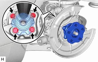
- Remove the 4 bolts, rear axle hub and bearing assembly and rear disc brake dust cover sub-assembly from the rear axle carrier sub-assembly.
- Put matchmarks on the rear drive shaft assembly and rear axle hub and bearing assembly.