Installation [12/2019 - 11/2023]: Procedure
- INSTALL BATTERY VOLTAGE SENSOR
See step 1
- INSTALL NO. 6 HV BATTERY CARRIER BRACKET
See step 2
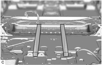
- INSTALL HYBRID BATTERY TERMINAL BLOCK
Refer to PROCEDURE - Step 1
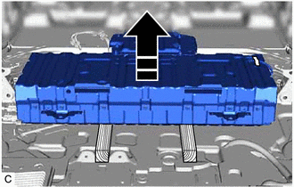
- INSTALL NO. 1 HYBRID BATTERY SHIELD SUB-ASSEMBLY
Refer to PROCEDURE - Step 2
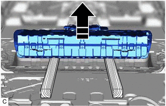
- INSTALL HV BATTERY JUNCTION BLOCK ASSEMBLY
Refer to PROCEDURE - Step 1
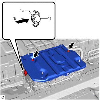
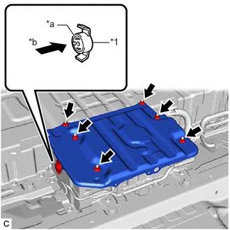
- INSTALL NO. 10 HV BATTERY SHIELD PANEL
- Install the No. 10 HV battery shield panel to the HV battery with the 6 nuts.
Torque: 7.5 N.m (76 kgf/cm, 66 in.lbf)
- Install the No. 10 HV battery shield panel to the HV battery with the 6 nuts.
- INSTALL HV BATTERY WARNING:
Be sure to wear insulated gloves.
- Set wooden blocks as shown in the illustration.
- Using a suitable adaptor such as straps, install the HV battery while tilting it.WARNING:
To prevent any accidents and injuries due to the weight of the HV battery, follow all specified procedures and be careful to balance the HV battery when removing or installing it.
NOTE:- To prevent the wire harness from being caught, make sure to bundle the wire harness using insulating tape or equivalent.
- Use cardboard or another similar material to protect the HV battery and vehicle body from damage.
- Since the HV battery is very heavy, 2 people are needed to install it. When installing the HV battery, be careful not to damage the parts around it.
- When removing/installing/moving the HV battery, make sure not to tilt it more than 80°.
- While lowering the HV battery into the vehicle, do not allow it to contact the vehicle.
- If the HV battery has been struck or dropped, replace it.
- Push the HV battery to the front of the vehicle as shown in the illustration.
- Install the No. 2 HV battery intake duct RH to the HV battery with the clip.
- Engage the 2 claws of hybrid battery thermistor (sensor portion) to connect the hybrid battery thermistor to the No. 2 HV battery intake duct RH.
- Engage the clamp.
- Install the No. 2 HV battery intake duct LH to the HV battery with the clip.
- Tilt the HV battery and remove the wooden blocks.
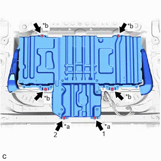
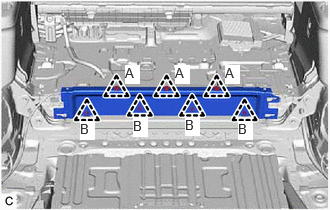
- Temporarily install the HV battery to the vehicle body with the 2 bolts (A) and 4 bolts (B).
*a Bolt (A)
(Bolt Length: 24 mm (0.945 in.))*b Bolt (B)
(Bolt Length: 25 mm (0.984 in.))NOTE:- Do not allow foreign matter, such as grease or oil, to adhere to the bolts of the HV battery.
- As bolts with 2 different lengths are used, make sure to install each bolt to the correct position.
- Fully tighten the 2 bolts (A) in the order shown in the illustration.
Torque: 19 N.m (194 kgf/cm, 14 ft.lbf)
- Fully tighten the 4 bolts (B).
Torque: 19 N.m (194 kgf/cm, 14 ft.lbf)
- Set wooden blocks as shown in the illustration.
- REMOVE NO. 10 HV BATTERY SHIELD PANEL
See step 25 [12/2019 - 10/2022], or see step 20 [10/2022 - 11/2023]
- CONNECT FLOOR WIRE WARNING:
Be sure to wear insulated gloves.
- Engage the 3 clamps to connect the floor wire.
- Connect the electric vehicle battery plug assembly connector.
- w/ 1500w Voltage Inverter
- Connect the shield ground with the nut.
Torque: 8.0 N.m (82 kgf/cm, 71 in.lbf)
- Engage the claw.
- Connect the 2 HV battery junction block assembly connectors.NOTE:
Make sure that the connectors are connected securely.
- Connect the shield ground with the nut.
- Connect the HV battery junction block assembly connector.NOTE:
Make sure that the connector is connected securely.
- Connect the floor wire connector.
- Engage the 2 clamps.
- CONNECT FLOOR UNDER WIRE WARNING:
Be sure to wear insulated gloves.
- Connect the shield ground to the HV battery.
- Engage the clamp.
- Connect the 2 HV battery junction block assembly connectors.NOTE:
Make sure that the connectors are connected securely.
- INSTALL NO. 10 HV BATTERY SHIELD PANEL WARNING:
Be sure to wear insulated gloves.
- for Captain Seat Type:
- Install the No. 10 HV battery shield panel to the HV battery with the 2 nuts.
Torque: 7.5 N.m (76 kgf/cm, 66 in.lbf)
*1 Battery Cover Lock Striker *a Button *b Push - Install the battery cover lock striker, then push the button to lock it.
- Install the No. 4 console box mounting bracket to the HV battery with the 2 nuts.
Torque: 7.5 N.m (76 kgf/cm, 66 in.lbf)
- Install the No. 3 console box mounting bracket to the HV battery with the 2 nuts.
Torque: 7.5 N.m (76 kgf/cm, 66 in.lbf)
- Install the No. 10 HV battery shield panel to the HV battery with the 2 nuts.
- for 60/40 Split Seat Type:
- for Captain Seat Type:
- INSTALL VOLTAGE INVERTER ASSEMBLY (w/ Voltage Inverter)
Refer to INSTALLATION [12/2019 - ]
- INSTALL REAR SEAT SUB FLOOR PANEL ASSEMBLY
- Install the rear seat sub floor panel assembly with the 6 bolts.
Torque: 38 N.m (387 kgf/cm, 28 ft.lbf)
- Connect the connector.
- Install the rear seat sub floor panel assembly with the 6 bolts.
- INSTALL CENTER PROTECTOR COVER
- INSTALL FRONT DECK SIDE TRIM COVER LH
Refer to PROCEDURE - Step 30 [12/2019 - 10/2022] , or refer to PROCEDURE - Step 28 [10/2022 - ]
- INSTALL FRONT DECK SIDE TRIM COVER RH
Refer to PROCEDURE - Step 41 [12/2019 - 10/2022] , or refer to PROCEDURE - Step 39 [10/2022 - ]
- INSTALL REAR NO. 2 SEAT ASSEMBLY
Refer to INSTALLATION [12/2019 - ]
- INSTALL NO. 1 FLOOR BOARD
- Install the No. 1 floor board.
- INSTALL NO. 2 FLOOR BOARD
- Install the No. 2 floor board.
- INSTALL NO. 3 FLOOR BOARD
- Install the No. 3 floor board.
- INSTALL BATTERY COOLING BLOWER ASSEMBLY
Refer to INSTALLATION [12/2019 - ]
- INSTALL SERVICE PLUG GRIP
Refer to INSTALLATION [12/2019 - 11/2023]
- PERFORM INITIALIZATION
Refer to INITIALIZATION [12/2019 - 09/2020] , or refer to INITIALIZATION [09/2020 - 10/2021] , or refer to INITIALIZATION [10/2021 - 10/2022] , or refer to INITIALIZATION [10/2022 - 11/2023]