DTC P2120-12: Throttle/Pedal Position Sensor/Switch "D" Circuit Short to Battery; DTC P2120-14: Throttle/Pedal Position Sensor/Switch "D" Circuit Short to Ground or Open; DTC P2120-1C: Throttle/Pedal Position Sensor/Switch "D" Circuit Voltage Out of Range; DTC P2120-1F: Throttle/Pedal Position Sensor/Switch "D" Circuit Intermittent; DTC P2120-99: Throttle/Pedal Position Sensor/Switch "D" Exceeded Learning Limit; DTC P2125-12: Throttle/Pedal Position Sensor/Switch "E" Circuit Short to Battery; DTC P2125-14: Throttle/Pedal Position Sensor/Switch "E" Circuit Short to Ground or Open; DTC P2125-1F: Throttle/Pedal Position Sensor/Switch "E" Circuit Intermittent; DTC P2138-2B: Throttle/Pedal Position Sensor/Switch "D"/"E" Voltage Correlation Signal Cross Coupled [12/2019 - 10/2022]: Procedure
- READ VALUE USING GTS (ACCELERATOR PEDAL POSITION SENSOR)
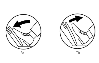
*a Fully Depressed *b Fully Released - Read the value displayed on the GTS.
Powertrain > Engine > Data List
Tester Display Accelerator Position Sensor No. 1 Voltage Accelerator Position Sensor No. 2 Voltage Standard Voltage
Accelerator Pedal Operation Accelerator Position Sensor No. 1 Voltage Accelerator Position Sensor No. 2 Voltage Difference between Accelerator Position Sensor No. 1 Voltage and Accelerator Position Sensor No. 2 Voltage Fully Released 0.5 to 1.1 V 1.2 to 2.0 V More than 0.02 V Fully Depressed 2.6 to 4.5 V 3.4 to 4.75 V Result
Proceed to OK NG
Result:
OK
CHECK FOR INTERMITTENT PROBLEMS
Refer to CHECK FOR INTERMITTENT PROBLEMS [12/2019 - 10/2022]
Result:
NG
See step 2
- Read the value displayed on the GTS.
- CHECK TERMINAL VOLTAGE (POWER SOURCE OF ACCELERATOR PEDAL SENSOR ASSEMBLY)
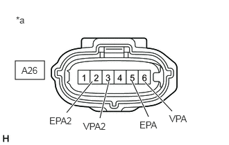
*a Front view of wire harness connector
(to Accelerator Pedal Sensor Assembly)HINT:
Make sure that the connector is properly connected. If it is not, securely connect it and check for DTCs again.
- Disconnect the accelerator pedal sensor assembly connector.
- Turn the ignition switch to ON.
- Measure the voltage according to the value(s) in the table below.
Standard Voltage
Tester Connection Condition Specified Condition A26-4 (VCPA) - A26-5 (EPA) Ignition switch ON 4.5 to 5.5 V A26-1 (VCP2) - A26-2 (EPA2) Ignition switch ON 4.5 to 5.5 V Result
Proceed to OK NG
Result:
NG
See step 5
Result:
OK
See step 3
- CHECK HARNESS AND CONNECTOR (RESISTANCE OF ECM)
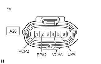
*a Front view of wire harness connector
(to Accelerator Pedal Sensor Assembly)- Disconnect the accelerator pedal sensor assembly connector.
- Measure the resistance according to the value(s) in the table below.
Standard Resistance
Tester Connection Condition Specified Condition A26-6 (VPA) - A26-5 (EPA) Ignition switch off 37.05 to 40.95 kΩ A26-3 (VPA2) - A26-2 (EPA2) Ignition switch off 37.05 to 40.95 kΩ Result
Proceed to OK NG
Result:
OK
REPLACE ACCELERATOR PEDAL (W/SENSOR) ROD ASSEMBLY
Refer to REMOVAL [12/2019 - 10/2022]
Result:
NG
See step 4
- CHECK HARNESS AND CONNECTOR (ACCELERATOR PEDAL SENSOR ASSEMBLY - ECM)
- Disconnect the accelerator pedal sensor assembly connector.
- Disconnect the ECM connector.
- Measure the resistance according to the value(s) in the table below.
Standard Resistance
Tester Connection Condition Specified Condition A26-6 (VPA) - A28-47 (VPA) Always Below 1 Ω A26-5 (EPA) - A28-48 (EPA) Always Below 1 Ω A26-3 (VPA2) - A28-50 (VPA2) Always Below 1 Ω A26-2 (EPA2) - A28-51 (EPA2) Always Below 1 Ω A26-6 (VPA) or A28-47 (VPA) - Body ground and other terminals Always 10 kΩ or higher A26-5 (EPA) or A28-48 (EPA) - Body ground and other terminals Always 10 kΩ or higher A26-3 (VPA2) or A28-50 (VPA2) - Body ground and other terminals Always 10 kΩ or higher A26-2 (EPA2) or A28-51 (EPA2) - Body ground and other terminals Always 10 kΩ or higher Result
Proceed to OK NG
Result:
OK
REPLACE ECM
Refer to REMOVAL [12/2019 - 09/2020] , or refer to REMOVAL [09/2020 - 10/2022]
Result:
NG
REPAIR OR REPLACE HARNESS OR CONNECTOR
- CHECK HARNESS AND CONNECTOR (ACCELERATOR PEDAL SENSOR ASSEMBLY - ECM)
- Disconnect the accelerator pedal sensor assembly connector.
- Disconnect the ECM connector.
- Measure the resistance according to the value(s) in the table below.
Standard Resistance
Tester Connection Condition Specified Condition A26-4 (VCPA) - A28-49 (VCPA) Always Below 1 Ω A26-5 (EPA) - A28-48 (EPA) Always Below 1 Ω A26-1 (VCP2) - A28-52 (VCP2) Always Below 1 Ω A26-2 (EPA2) - A28-51 (EPA2) Always Below 1 Ω A26-4 (VCPA) or A28-49 (VCPA) - Body ground and other terminals Always 10 kΩ or higher A26-5 (EPA) or A28-48 (EPA) - Body ground and other terminals Always 10 kΩ or higher A26-1 (VCP2) or A28-52 (VCP2) - Body ground and other terminals Always 10 kΩ or higher A26-2 (EPA2) or A28-51 (EPA2) - Body ground and other terminals Always 10 kΩ or higher Result
Proceed to OK NG
Result:
OK
REPLACE ECM
Refer to REMOVAL [12/2019 - 09/2020] , or refer to REMOVAL [09/2020 - 10/2022]
Result:
NG
REPAIR OR REPLACE HARNESS OR CONNECTOR