DTC P2135-2B: Throttle/Pedal Position Sensor/Switch "A"/"B" Voltage Correlation Signal Cross Coupled [12/2019 - 10/2022]: Procedure
- READ VALUE USING GTS (THROTTLE POSITION SENSOR VOLTAGE)
- Read the values displayed on the GTS.
Powertrain > Engine > Data List
Tester Display Throttle Position Sensor No. 1 Voltage Throttle Position Sensor No. 2 Voltage Result
Result Proceed to Value of both Throttle Position Sensor No. 1 Voltage and Throttle Position Sensor No. 2 Voltage are less than 0.56 V A Value of both Throttle Position Sensor No. 1 Voltage and Throttle Position Sensor No. 2 Voltage are higher than 4.535 V B Value of both Throttle Position Sensor No. 1 Voltage and Throttle Position Sensor No. 2 Voltage are between 0.56 V and 4.535 V C
Result:
B
See step 4
Result:
C
See step 6
Result:
A
See step 2
- Read the values displayed on the GTS.
- CHECK HARNESS AND CONNECTOR (THROTTLE POSITION SENSOR - ECM)
- Disconnect the throttle body with motor assembly connector.
- Disconnect the ECM connector.
- Measure the resistance according to the value(s) in the table below.
Standard Resistance
Tester Connection Condition Specified Condition C26-5 (VC) - C54-121 (VCTA) Always Below 1 Ω C26-6 (VTA) - C54-122 (VTA1) Always Below 1 Ω C26-4 (VTA2) - C54-89 (VTA2) Always Below 1 Ω C26-3 (E2) - C54-120 (ETA) Always Below 1 Ω C26-5 (VC) or C54-121 (VCTA) - Body ground and other terminals Always 10 kΩ or higher C26-6 (VTA) or C54-122 (VTA1) - Body ground and other terminals Always 10 kΩ or higher C26-4 (VTA2) or C54-89 (VTA2) - Body ground and other terminals Always 10 kΩ or higher Result
Proceed to OK NG
Result:
NG
REPAIR OR REPLACE HARNESS OR CONNECTOR
Result:
OK
See step 3
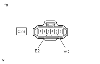
- INSPECT TERMINAL VOLTAGE (POWER SOURCE OF THROTTLE POSITION SENSOR)
*a Front view of wire harness connector
(to Throttle Body with Motor Assembly)- Disconnect the throttle body with motor assembly connector.
- Turn the ignition switch to ON.
- Measure the voltage according to the value(s) in the table below.
Standard Voltage
Tester Connection Condition Specified Condition C26-5 (VC) - C26-3 (E2) Ignition switch ON 4.5 to 5.5 V HINT:
Perform "Inspection After Repair" after replacing the throttle body with motor assembly.
Refer to INITIALIZATION [12/2019 - 10/2022]
Result
Proceed to OK NG
Result:
OK
REPLACE THROTTLE BODY WITH MOTOR ASSEMBLY. Refer to REMOVAL [12/2019 - 10/2022]
Result:
NG
REPLACE ECM. Refer to REMOVAL [12/2019 - 09/2020] , or refer to REMOVAL [09/2020 - 10/2022]
- CHECK HARNESS AND CONNECTOR (GROUND CIRCUIT)
HINT:
Make sure that the connector is properly connected. If it is not, securely connect it and check for DTCs again.
- Disconnect the throttle body with motor assembly connector.
- Measure the resistance according to the value(s) in the table below.
Standard Resistance
Tester Connection Condition Specified Condition C26-3 (E2) - Body ground Always Below 1 Ω HINT:
Perform "Inspection After Repair" after replacing the throttle body with motor assembly.
Refer to INITIALIZATION [12/2019 - 10/2022]
Result
Proceed to OK NG
Result:
OK
REPLACE THROTTLE BODY WITH MOTOR ASSEMBLY. Refer to REMOVAL [12/2019 - 10/2022]
Result:
NG
See step 5
- CHECK HARNESS AND CONNECTOR (THROTTLE POSITION SENSOR - ECM)
- Disconnect the throttle body with motor assembly connector.
- Disconnect the ECM connector.
- Measure the resistance according to the value(s) in the table below.
Standard Resistance
Tester Connection Condition Specified Condition C26-5 (VC) - C54-121 (VCTA) Always Below 1 Ω C26-6 (VTA) - C54-122 (VTA1) Always Below 1 Ω C26-4 (VTA2) - C54-89 (VTA2) Always Below 1 Ω C26-3 (E2) - C54-120 (ETA) Always Below 1 Ω C26-5 (VC) or C54-121 (VCTA) - Other terminals Always 10 kΩ or higher C26-6 (VTA) or C54-122 (VTA1) - Other terminals Always 10 kΩ or higher C26-4 (VTA2) or C54-89 (VTA2) - Other terminals Always 10 kΩ or higher Result
Proceed to OK NG
Result:
OK
REPLACE ECM. Refer to REMOVAL [12/2019 - 09/2020] , or refer to REMOVAL [09/2020 - 10/2022]
Result:
NG
REPAIR OR REPLACE HARNESS OR CONNECTOR
- CHECK HARNESS AND CONNECTOR (SHORT CIRCUIT)
- Disconnect the throttle body with motor assembly connector.
- Measure the resistance according to the value(s) in the table below.
Standard Resistance
Tester Connection Condition Specified Condition C26-6 (VTA) - C26-4 (VTA2) Always 10 kΩ or higher HINT:
Perform "Inspection After Repair" after replacing the throttle body with motor assembly.
Refer to INITIALIZATION [12/2019 - 10/2022]
Result
Proceed to OK NG
Result:
OK
REPLACE THROTTLE BODY WITH MOTOR ASSEMBLY. Refer to REMOVAL [12/2019 - 10/2022]
Result:
NG
See step 7
- CHECK HARNESS AND CONNECTOR (SHORT CIRCUIT)
- Disconnect the throttle body with motor assembly connector.
- Disconnect the ECM connector.
- Measure the resistance according to the value(s) in the table below.
Standard Resistance
Tester Connection Condition Specified Condition C26-6 (VTA) - C26-4 (VTA2) Always 10 kΩ or higher HINT:
If the resistance changes when the ECM connector is disconnected, there is an internal short in the ECM.
Result
Proceed to OK NG
Result:
OK
REPLACE ECM. Refer to REMOVAL [12/2019 - 09/2020] , or refer to REMOVAL [09/2020 - 10/2022]
Result:
NG
REPAIR OR REPLACE HARNESS OR CONNECTOR (THROTTLE POSITION SENSOR - ECM)