VC Output Circuit [12/2019 - 10/2022]: Procedure
- CHECK CONNECTION BETWEEN GTS AND ECM
- Check the communication between the GTS and ECM.
HINT:
It can be checked using the "Engine" item of the Data List.
Result
Result Proceed to Communication is not possible A Communication is possible B
Result:
B
PROCEED TO NEXT SUSPECTED AREA SHOWN IN PROBLEM SYMPTOMS TABLE. Refer to PROBLEM SYMPTOMS TABLE [12/2019 - 10/2022]
Result:
A
See step 2
- Check the communication between the GTS and ECM.
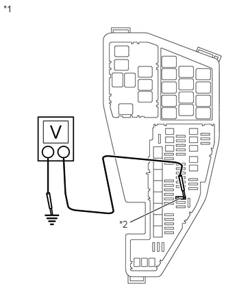
- CHECK EFI NO. 4 FUSE VOLTAGE
*1 No. 1 Engine Room Relay Block and No. 1 Junction Block Assembly *2 EFI NO. 4 Fuse - Turn the ignition switch to ON.
- Measure the voltage according to the value(s) in the table below.
Standard Voltage
Tester Connection Condition Specified Condition 1 (EFI NO. 4 fuse) - Body ground Ignition switch ON 11 to 14 V HINT:
- Check the fuse with it installed to the engine room relay block and junction block assembly.
- If the result is not as specified, since current is not flowing to the +B and +B2 terminals of the ECM, the system may not be started.
Result
Proceed to OK NG
Result:
NG
GO TO ECM POWER SOURCE CIRCUIT. Refer to ECM Power Source Circuit [12/2019 - 10/2022]
Result:
OK
See step 3
- CHECK CONNECTION BETWEEN GTS AND ECM (THROTTLE POSITION SENSOR)
- Disconnect the throttle body with motor assembly connector.
- Check the communication between the GTS and ECM.
HINT:
It can be checked using the "Engine" item of the Data List.
Result
Result Proceed to Communication is not possible A Communication is possible B HINT:
Perform "Inspection After Repair" after replacing the throttle body with motor assembly.
Refer to INITIALIZATION [12/2019 - 10/2022]
Result:
B
REPLACE THROTTLE BODY WITH MOTOR ASSEMBLY. Refer to REMOVAL [12/2019 - 10/2022]
Result:
A
See step 4
- CHECK CONNECTION BETWEEN GTS AND ECM (ACCELERATOR PEDAL POSITION SENSOR)
- Disconnect the accelerator pedal sensor assembly connector.
- Check the communication between the GTS and ECM.
HINT:
It can be checked using the "Engine" item of the Data List.
Result
Result Proceed to Communication is not possible A Communication is possible B
Result:
B
REPLACE ACCELERATOR PEDAL (W/SENSOR) ROD ASSEMBLY. Refer to REMOVAL [12/2019 - 10/2022]
Result:
A
See step 5
- CHECK CONNECTION BETWEEN GTS AND ECM (CRANKSHAFT POSITION SENSOR)
- Disconnect the crankshaft position sensor connector.
- Check the communication between the GTS and ECM.
HINT:
It can be checked using the "Engine" item of the Data List.
Result
Result Proceed to Communication is not possible A Communication is possible B
Result:
B
REPLACE CRANKSHAFT POSITION SENSOR. Refer to REMOVAL [12/2019 - 10/2022]
Result:
A
See step 6
- CHECK CONNECTION BETWEEN GTS AND ECM (VVT SENSOR (FOR INTAKE CAMSHAFT OF BANK 1))
- Disconnect the VVT sensor (for intake camshaft of bank 1) connector.
- Check the communication between the GTS and ECM.
HINT:
It can be checked using the "Engine" item of the Data List.
Result
Result Proceed to Communication is not possible A Communication is possible B
Result:
B
REPLACE VVT SENSOR (FOR INTAKE CAMSHAFT OF BANK 1). Refer to REMOVAL [12/2019 - 10/2022]
Result:
A
See step 7
- CHECK CONNECTION BETWEEN GTS AND ECM (VVT SENSOR (FOR INTAKE CAMSHAFT OF BANK 2))
- Disconnect the VVT sensor (for intake camshaft of bank 2) connector.
- Check the communication between the GTS and ECM.
HINT:
It can be checked using the "Engine" item of the Data List.
Result
Result Proceed to Communication is not possible A Communication is possible B
Result:
B
REPLACE VVT SENSOR (FOR INTAKE CAMSHAFT OF BANK 2). Refer to REMOVAL [12/2019 - 10/2022]
Result:
A
See step 8
- CHECK CONNECTION BETWEEN GTS AND ECM (VVT SENSOR (FOR EXHAUST CAMSHAFT OF BANK 1))
- Disconnect the VVT sensor (for exhaust camshaft of bank 1) connector.
- Check the communication between the GTS and ECM.
HINT:
It can be checked using the "Engine" item of the Data List.
Result
Result Proceed to Communication is not possible A Communication is possible B
Result:
B
REPLACE VVT SENSOR (FOR EXHAUST CAMSHAFT OF BANK 1). Refer to REMOVAL [12/2019 - 10/2022]
Result:
A
See step 9
- CHECK CONNECTION BETWEEN GTS AND ECM (VVT SENSOR (FOR EXHAUST CAMSHAFT OF BANK 2))
- Disconnect the VVT sensor (for exhaust camshaft of bank 2) connector.
- Check the communication between the GTS and ECM.
HINT:
It can be checked using the "Engine" item of the Data List.
Result
Result Proceed to Communication is not possible A Communication is possible B
Result:
B
REPLACE VVT SENSOR (FOR EXHAUST CAMSHAFT OF BANK 2). Refer to REMOVAL [12/2019 - 10/2022]
Result:
A
See step 10
- CHECK CONNECTION BETWEEN GTS AND ECM (FUEL PRESSURE SENSOR (FOR HIGH PRESSURE SIDE))
- Disconnect the fuel pressure sensor (for high pressure side) connector.
- Check the communication between the GTS and ECM.
HINT:
It can be checked using the "Engine" item of the Data List.
Result
Result Proceed to Communication is not possible A Communication is possible B HINT:
Perform "Inspection After Repair" after replacing the fuel pressure sensor (for high pressure side).
Refer to INITIALIZATION [12/2019 - 10/2022]
Result:
B
REPLACE FUEL DELIVERY PIPE WITH SENSOR ASSEMBLY LH. Refer to REMOVAL [12/2019 - 10/2022]
Result:
A
See step 11
- CHECK CONNECTION BETWEEN GTS AND ECM (FUEL PRESSURE SENSOR (FOR LOW PRESSURE SIDE))
- Disconnect the fuel pressure sensor (for low pressure side) connector.
- Check the communication between the GTS and ECM.
HINT:
It can be checked using the "Engine" item of the Data List.
Result
Result Proceed to Communication is not possible A Communication is possible B HINT:
Perform "Inspection After Repair" after replacing the fuel pressure sensor (for low pressure side).
Refer to INITIALIZATION [12/2019 - 10/2022]
Result:
B
REPLACE FUEL DELIVERY PIPE WITH SENSOR ASSEMBLY. Refer to REMOVAL [12/2019 - 10/2022]
Result:
A
See step 12
- CHECK CONNECTION BETWEEN GTS AND ECM (MASS AIR FLOW METER SUB-ASSEMBLY)
- Disconnect the mass air flow meter sub-assembly connector.
- Check the communication between the GTS and ECM.
HINT:
It can be checked using the "Engine" item of the Data List.
Result
Result Proceed to Communication is not possible A Communication is possible B
Result:
B
REPLACE MASS AIR FLOW METER SUB-ASSEMBLY. Refer to REMOVAL [12/2019 - 10/2022]
Result:
A
See step 13
- CHECK CONNECTION BETWEEN GTS AND ECM (CANISTER PUMP MODULE)
- Disconnect the canister pump module connector.
- Check the communication between the GTS and ECM.
HINT:
It can be checked using the "Engine" item of the Data List.
Result
Result Proceed to Communication is not possible A Communication is possible B
Result:
B
REPLACE CANISTER PUMP MODULE. Refer to REMOVAL [12/2019 - 10/2022]
Result:
A
See step 14
- CHECK HARNESS AND CONNECTOR
- Disconnect the throttle body with motor assembly connector.
- Disconnect the accelerator pedal sensor assembly connector.
- Disconnect the crankshaft position sensor connector.
- Disconnect the VVT sensor (for intake camshaft of bank 1) connector.
- Disconnect the VVT sensor (for intake camshaft of bank 2) connector.
- Disconnect the VVT sensor (for exhaust camshaft of bank 1) connector.
- Disconnect the VVT sensor (for exhaust camshaft of bank 2) connector.
- Disconnect the fuel pressure sensor (for high pressure side) connector.
- Disconnect the fuel pressure sensor (for low pressure side) connector.
- Disconnect the mass air flow meter sub-assembly connector.
- Disconnect the ECM connectors.
- Disconnect the canister pump module connector.
- Measure the resistance according to the value(s) in the table below.
Standard Resistance
Tester Connection Condition Specified Condition C54-121 (VCTA) - Body ground Always 10 kΩ or higher A28-49 (VCPA) - Body ground Always 10 kΩ or higher A28-52 (VCP2) - Body ground Always 10 kΩ or higher C54-96 (VCNE) - Body ground Always 10 kΩ or higher C54-99 (VCV1) - Body ground Always 10 kΩ or higher C54-98 (VCV2) - Body ground Always 10 kΩ or higher C54-90 (VC) - Body ground Always 10 kΩ or higher A28-35 (VCPP) - Body ground Always 10 kΩ or higher - Remove the FUEL PMP relay and A/F HTR relay from the No. 1 engine room relay block and No. 1 junction block assembly.
HINT:
Remove the FUEL PMP and A/F HTR relays connected between the checked terminals as the coil inside the relay influences the measurement value.
- Measure the resistance according to the value(s) in the table below.
Standard Resistance
Tester Connection Condition Specified Condition A28-2 (+B) - 1 (EFI NO. 4 fuse) Always Below 1 Ω A28-3 (+B2) - 1 (EFI NO. 4 fuse) Always Below 1 Ω A28-2 (+B) - Body ground Always 10 kΩ or higher A28-3 (+B2) - Body ground Always 10 kΩ or higher Result
Proceed to OK NG
Result:
OK
REPLACE ECM. Refer to REMOVAL [12/2019 - 09/2020] , or refer to REMOVAL [09/2020 - 10/2022]
Result:
NG
REPAIR OR REPLACE HARNESS OR CONNECTOR