DTC P26CA-31: Engine Coolant Pump No Signal [12/2019 - 10/2022]: Procedure
- CHECK TERMINAL VOLTAGE (POWER SOURCE OF WATER INLET HOUSING WITH WATER PUMP SUB-ASSEMBLY)
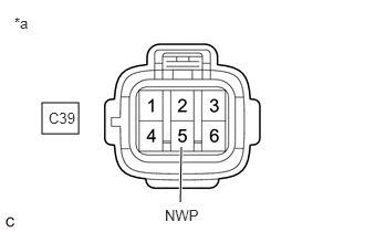
*a Front view of wire harness connector
(to Water Inlet Housing with Water Pump Sub-assembly)- Disconnect the water inlet housing with water pump sub-assembly connector.
- Turn the ignition switch to ON.
- Measure the voltage according to the value(s) in the table below.
Standard Voltage
Tester Connection Condition Specified Condition C39-5 (NWP) - Body ground Ignition switch ON 11 to 14 V Result
Proceed to OK NG
Result:
NG
See step 8
Result:
OK
See step 2
- CHECK HARNESS AND CONNECTOR (WATER INLET HOUSING WITH WATER PUMP SUB-ASSEMBLY - BODY GROUND)
- Disconnect the water inlet housing with water pump sub-assembly connector.
- Measure the resistance according to the value(s) in the table below.
Standard Resistance
Tester Connection Condition Specified Condition C39-3 (PGN2) - Body ground Always Below 1 Ω C39-6 (PGND) - Body ground Always Below 1 Ω Result
Proceed to OK NG
Result:
NG
REPAIR OR REPLACE HARNESS OR CONNECTOR
Result:
OK
See step 3
- CHECK TERMINAL VOLTAGE (POWER SOURCE OF WATER INLET HOUSING WITH WATER PUMP SUB-ASSEMBLY)
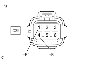
*a Front view of wire harness connector
(to Water Inlet Housing with Water Pump Sub-assembly)- Disconnect the water inlet housing with water pump sub-assembly connector.
- Turn the ignition switch to ON.
- Measure the voltage according to the value(s) in the table below.
Standard Voltage
Tester Connection Condition Specified Condition C39-1 (+B2) - Body ground Ignition switch ON 11 to 14 V C39-4 (+B) - Body ground Ignition switch ON 11 to 14 V Result
Proceed to OK NG
Result:
OK
REPLACE WATER INLET HOUSING WITH WATER PUMP SUB-ASSEMBLY
Refer to REMOVAL [12/2019 - ]
Result:
NG
See step 4
- INSPECT EFI-MAIN NO. 3 RELAY
Refer to PROCEDURE - Step 3
Result
Proceed to OK NG Result:
NG
REPLACE EFI-MAIN NO. 3 RELAY
Result:
OK
See step 5
- CHECK HARNESS AND CONNECTOR (POWER SOURCE OF EFI-MAIN NO. 3 RELAY)
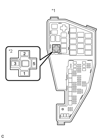
*1 No. 1 Engine Room Relay Block and No. 1 Junction Block Assembly *2 EFI-MAIN NO. 3 Relay - Remove the EFI-MAIN NO. 3 relay from the No. 1 engine room relay block and No. 1 junction block assembly.
- Measure the voltage according to the value(s) in the table below.
Standard Voltage
Tester Connection Condition Specified Condition 3 (EFI-MAIN NO. 3 relay) - Body ground Always 11 to 14 V Result
Proceed to OK NG
Result:
NG
REPAIR OR REPLACE HARNESS OR CONNECTOR (AUXILIARY BATTERY - EFI-MAIN NO. 3 RELAY)
Result:
OK
See step 6
- CHECK HARNESS AND CONNECTOR (EFI-MAIN NO. 3 RELAY - BODY GROUND)
- Remove the EFI-MAIN NO. 3 relay from the No. 1 engine room relay block and No. 1 junction block assembly.
- Measure the resistance according to the value(s) in the table below.
Standard Resistance
Tester Connection Condition Specified Condition 1 (EFI-MAIN NO. 3 relay) - Body ground Always Below 1 Ω Result
Proceed to OK NG
Result:
NG
REPAIR OR REPLACE HARNESS OR CONNECTOR
Result:
OK
See step 7
- CHECK HARNESS AND CONNECTOR (EFI-MAIN NO. 3 RELAY - WATER INLET HOUSING WITH WATER PUMP SUB-ASSEMBLY)
- Remove the EFI-MAIN NO. 3 relay from the No. 1 engine room relay block and No. 1 junction block assembly.
- Disconnect the water inlet housing with water pump sub-assembly connector.
- Measure the resistance according to the value(s) in the table below.
Standard Resistance
Tester Connection Condition Specified Condition 5 (EFI-MAIN NO. 3 relay) - C39-1 (+B2) Always Below 1 Ω 5 (EFI-MAIN NO. 3 relay) - C39-4 (+B) Always Below 1 Ω 5 (EFI-MAIN NO. 3 relay), C39-1 (+B2) or C39-4 (+B) - Body ground and other terminals Always 10 kΩ or higher Result
Proceed to OK NG
Result:
OK
REPAIR OR REPLACE HARNESS OR CONNECTOR (EFI-MAIN NO. 1 RELAY - EFI-MAIN NO. 3 RELAY)
Result:
NG
REPAIR OR REPLACE HARNESS OR CONNECTOR
- CHECK HARNESS AND CONNECTOR (WATER INLET HOUSING WITH WATER PUMP SUB-ASSEMBLY - ECM)
- Disconnect the water inlet housing with water pump sub-assembly connector.
- Disconnect the ECM connector.
- Measure the resistance according to the value(s) in the table below.
Standard Resistance
Tester Connection Condition Specified Condition C39-5 (NWP) - C55-51 (WPI) Always Below 1 Ω C39-5 (NWP) or C55-51 (WPI) - Body ground and other terminals Always 10 kΩ or higher Result
Proceed to OK NG
Result:
OK
REPLACE ECM
Refer to REMOVAL [12/2019 - 10/2022]
Result:
NG
REPAIR OR REPLACE HARNESS OR CONNECTOR