DTC P1360-01: "A" Camshaft Position Actuator Bank 1 General Electrical Failure [10/2022 - 11/2023]: Procedure
- CHECK TERMINAL VOLTAGE (POWER SOURCE OF CAM TIMING CONTROL MOTOR WITH EDU ASSEMBLY)
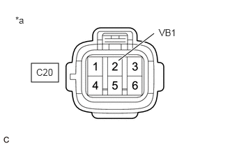
- Disconnect the cam timing control motor with EDU assembly connector.
*a Front view of wire harness connector
(to Cam Timing Control Motor with EDU Assembly) - Turn the ignition switch to ON.
- Measure the voltage according to the value(s) in the table below.
Standard Voltage
Tester Connection Condition Specified Condition C20-2 (VB1) - Body ground Ignition switch ON 11 to 14 V Result
Proceed to OK NG
Result:
NG
See step 8
Result:
OK
See step 2
- Disconnect the cam timing control motor with EDU assembly connector.
- CHECK HARNESS AND CONNECTOR (CAM TIMING CONTROL MOTOR WITH EDU ASSEMBLY - BODY GROUND)
- Disconnect the cam timing control motor with EDU assembly connector.
- Measure the resistance according to the value(s) in the table below.
Standard Resistance
Tester Connection Condition Specified Condition C20-3 (GND) - Body ground Always Below 1 Ω Result
Proceed to OK NG
Result:
NG
REPAIR OR REPLACE HARNESS OR CONNECTOR
Result:
OK
See step 3
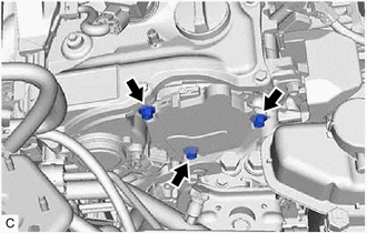
- INSPECT CAM TIMING CONTROL MOTOR WITH EDU ASSEMBLY (BODY GROUND)
- Check installation condition.
- Check that the 3 installation bolts of the cam timing control motor with EDU assembly are tightened to the specified torque.
Torque
21 N.m (214 kgf/cm, 15 ft.lbf)
Result
Proceed to OK NG
Result:
NG
TIGHTEN TO SPECIFIED TORQUE
Result:
OK
See step 4
- Check installation condition.
- CHECK HARNESS AND CONNECTOR (CAM TIMING CONTROL MOTOR WITH EDU ASSEMBLY - ECM)
- Disconnect the cam timing control motor with EDU assembly connector.
- Disconnect the ECM connector.
- Measure the resistance according to the value(s) in the table below.
Standard Resistance
Tester Connection Condition Specified Condition C20-6 (VTS) - C55-70 (EMR1) Always Below 1 Ω C20-6 (VTS) or C55-70 (EMR1) - Body ground and other terminals Always 10 kΩ or higher Result
Proceed to OK NG
Result:
NG
REPAIR OR REPLACE HARNESS OR CONNECTOR
Result:
OK
See step 5
- REPLACE CAM TIMING CONTROL MOTOR WITH EDU ASSEMBLY
Refer to REMOVAL [10/2022 - 11/2023]
HINT:
Perform "Inspection After Repair" after replacing the cam timing control motor with EDU assembly.
Refer to INITIALIZATION [10/2021 - ]
Result
Proceed to NEXT Result:
NEXT
See step 6
- CLEAR DTC
- Clear the DTCs.
Powertrain > Engine > Clear DTCs
- Turn the ignition switch off and wait for at least 30 seconds.
Result
Proceed to NEXT
Result:
NEXT
See step 7
- Clear the DTCs.
- CONFIRM WHETHER MALFUNCTION HAS BEEN SUCCESSFULLY REPAIRED
- Drive the vehicle in accordance with the driving pattern described in Confirmation Driving Pattern.
- Read the DTCs.
Powertrain > Engine > Trouble Codes
Result
Result Proceed to DTCs are not output A DTC P1360-01 is output B
Result:
A
END
Result:
B
REPLACE ECM
Refer to REMOVAL [10/2022 - 11/2023]
- INSPECT VVT RELAY
Refer to PROCEDURE - Step 5
Result
Proceed to OK NG Result:
NG
REPLACE VVT RELAY
Result:
OK
See step 9
- CHECK HARNESS AND CONNECTOR (VVT RELAY - CAM TIMING CONTROL MOTOR WITH EDU ASSEMBLY)
- Remove the VVT relay from No. 1 engine room relay block and No. 1 junction block assembly.
- Disconnect the cam timing control motor with EDU assembly connector.
- Measure the resistance according to the value(s) in the table below.
Standard Resistance
Tester Connection Condition Specified Condition 5 (VVT relay) - C20-2 (VB1) Always Below 1 Ω 5 (VVT relay) or C20-2 (VB1) - Body ground and other terminals Always 10 kΩ or higher Result
Proceed to OK NG
Result:
NG
REPAIR OR REPLACE HARNESS OR CONNECTOR
Result:
OK
See step 10
- CHECK HARNESS AND CONNECTOR (POWER SOURCE OF VVT RELAY)
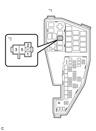
*1 No. 1 Engine Room Relay Block and No. 1 Junction Block Assembly *2 VVT Relay - Remove the VVT relay from No. 1 engine room relay block and No. 1 junction block assembly.
- Measure the voltage according to the value(s) in the table below.
Standard Voltage
Tester Connection Condition Specified Condition 3 (VVT relay) - Body ground Always 11 to 14 V Result
Proceed to OK NG
Result:
NG
REPAIR OR REPLACE HARNESS OR CONNECTOR (AUXILIARY BATTERY - VVT RELAY)
Result:
OK
See step 11
- CHECK HARNESS AND CONNECTOR (POWER SOURCE OF VVT RELAY)
*1 No. 1 Engine Room Relay Block and No. 1 Junction Block Assembly *2 VVT Relay - Remove the VVT relay from No. 1 engine room relay block and No. 1 junction block assembly.
- Turn the ignition switch to ON.
- Measure the voltage according to the value(s) in the table below.
Standard Voltage
Tester Connection Condition Specified Condition 1 (VVT relay) - Body ground Ignition switch ON 11 to 14 V Result
Proceed to OK NG
Result:
OK
REPAIR OR REPLACE HARNESS OR CONNECTOR (VVT RELAY - BODY GROUND)
Result:
NG
REPAIR OR REPLACE HARNESS OR CONNECTOR (EFI-MAIN NO. 1 RELAY - VVT RELAY)