DTC P0335-2A: Crankshaft Position Sensor "A" Signal Stuck in Range; DTC P0335-31: Crankshaft Position Sensor "A" No Signal [12/2019 - 10/2022]: Procedure
- READ VALUE USING GTS (ENGINE SPEED)
- Put the engine in Inspection Mode (Maintenance Mode).
Powertrain > Hybrid Control > Utility
Tester Display Inspection Mode - Start the engine.
- Read the values displayed on the GTS while the engine is running.
Powertrain > Engine > Data List
Tester Display Engine Speed Standard
Correct values are displayed.
HINT:
- To check the engine speed change, display the graph on the GTS.
- If the engine does not start, check the engine speed while cranking.
- If the engine speed indicated on the GTS remains at zero (0), there may be an open or short in the crankshaft position sensor circuit.
Result
Proceed to OK NG
Result:
OK
CHECK FOR INTERMITTENT PROBLEMS
Refer to CHECK FOR INTERMITTENT PROBLEMS [12/2019 - ]
Result:
NG
See step 2
- Put the engine in Inspection Mode (Maintenance Mode).
- CHECK HARNESS AND CONNECTOR
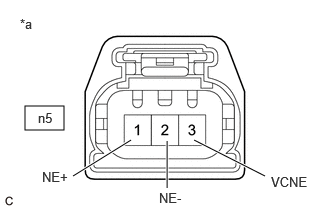
*a Front view of wire harness connector
(to Crankshaft Position Sensor)HINT:
Make sure that the connector is properly connected. If it is not, securely connect it and check for DTCs again.
- Disconnect the crankshaft position sensor connector.
- Turn the ignition switch to ON.
- Measure the voltage according to the value(s) in the table below.
Standard Voltage
Tester Connection Condition Specified Condition n5-3 (VCNE) - Body ground Ignition switch ON 4.5 to 5.5 V n5-1 (NE+) - Body ground Ignition switch ON 3.0 to 5.0 V - Turn the ignition switch off and wait for at least 30 seconds.
- Measure the resistance according to the value(s) in the table below.
Standard Resistance
Tester Connection Condition Specified Condition n5-3 (VCNE) - n5-1 (NE+) Ignition switch off 1.425 to 1.575 kΩ n5-2 (NE-) - Body ground Always Below 1 Ω Result
Proceed to OK NG
Result:
NG
See step 5
Result:
OK
See step 3
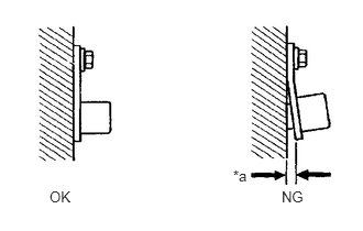
- CHECK SENSOR INSTALLATION AND CONDUCT VISUAL INSPECTION (CRANKSHAFT POSITION SENSOR)
*a Clearance - Visually check the crankshaft position sensor for damage.
- Check the crankshaft position sensor installation condition.
OK
The crankshaft position sensor does not have any damage and is installed properly.
Result
Proceed to OK NG
Result:
NG
SECURELY REINSTALL CRANKSHAFT POSITION SENSOR
Refer to INSTALLATION [12/2019 - 11/2023]
Result:
OK
See step 4
- INSPECT No. 1 CRANKSHAFT POSITION SENSOR PLATE (TEETH OF CRANKSHAFT POSITION SENSOR PLATE)
- Inspect the teeth of the No. 1 crankshaft position sensor plate.
OK
No. 1 crankshaft position sensor plate does not have any cracks or deformation.
Result
Proceed to OK NG
Result:
OK
REPLACE CRANKSHAFT POSITION SENSOR
Refer to REMOVAL [12/2019 - 10/2021] , or refer to REMOVAL [10/2021 - 11/2023]
Result:
NG
REPLACE NO. 1 CRANKSHAFT POSITION SENSOR PLATE
Refer to PROCEDURE - Step 4
- Inspect the teeth of the No. 1 crankshaft position sensor plate.
- CHECK HARNESS AND CONNECTOR (CRANKSHAFT POSITION SENSOR - ECM)
- Disconnect the crankshaft position sensor connector.
- Disconnect the ECM connector.
- Measure the resistance according to the value(s) in the table below.
Standard Resistance
Tester Connection Condition Specified Condition n5-3 (VCNE) - C55-116 (VCNE) Always Below 1 Ω n5-2 (NE-) - C55-115 (NE-) Always Below 1 Ω n5-1 (NE+) - C55-93 (NE+) Always Below 1 Ω n5-3 (VCNE) or C55-116 (VCNE) - Body ground and other terminals Always 10 kΩ or higher n5-2 (NE-) or C55-115 (NE-) - Body ground and other terminals Always 10 kΩ or higher n5-1 (NE+) or C55-93 (NE+) - Body ground and other terminals Always 10 kΩ or higher Result
Proceed to OK NG
Result:
OK
REPLACE ECM
Refer to REMOVAL [12/2019 - 10/2022]
Result:
NG
REPAIR OR REPLACE HARNESS OR CONNECTOR