DTC P0201-13: Cylinder 1 Injector "A" Circuit Open; DTC P0202-13: Cylinder 2 Injector "A" Circuit Open; DTC P0203-13: Cylinder 3 Injector "A" Circuit Open; DTC P0204-13: Cylinder 4 Injector "A" Circuit Open; DTC P062D-13: Fuel Injector Driver Circuit Performance Bank 1 Circuit Open [12/2019 - 10/2022]: Procedure
- CHECK DTC OUTPUT (DTC P0201-13, P0202-13, P0203-13, P0204-13 AND/OR P062D-13)
- Read the DTCs.
Powertrain > Engine > Trouble Codes
Result
Result Proceed to DTC P0201-13, P0202-13, P0203-13 or P0204-13 is output A 3 or more of the following DTCs are output: P062D-13, P0201-13, P0202-13, P0203-13 and P0204-13 B DTC P062D-13 is output
Result:
B
See step 4
Result:
A
See step 2
- Read the DTCs.
- CHECK HARNESS AND CONNECTOR
- Disconnect the ECM connector.
- Measure the resistance according to the value(s) in the table below.
Standard Resistance
Tester Connection Condition Specified Condition C55-16 (#1D+) - C55-17 (#1D-) 20°C (68°F) 1.34 to 1.64 Ω C55-11 (#2D+) - C55-10 (#2D-) 20°C (68°F) 1.34 to 1.64 Ω C55-12 (#3D+) - C55-13 (#3D-) 20°C (68°F) 1.34 to 1.64 Ω C55-15 (#4D+) - C55-14 (#4D-) 20°C (68°F) 1.34 to 1.64 Ω C55-16 (#1D+) or C55-17 (#1D-) - Body ground and other terminals Always 1 MΩ or higher C55-11 (#2D+) or C55-10 (#2D-) - Body ground and other terminals Always 1 MΩ or higher C55-12 (#3D+) or C55-13 (#3D-) - Body ground and other terminals Always 1 MΩ or higher C55-15 (#4D+) or C55-14 (#4D-) - Body ground and other terminals Always 1 MΩ or higher HINT:
The standard values shown are direct fuel injector assembly resistance values.
Result
Proceed to OK NG
Result:
OK
REPLACE ECM
Refer to REMOVAL [12/2019 - 10/2022]
Result:
NG
See step 3
- INSPECT DIRECT FUEL INJECTOR ASSEMBLY (RESISTANCE)
Refer to INSPECTION [12/2019 - ]
HINT:
Perform "Inspection After Repair" after replacing the direct fuel injector assembly.
Refer to INITIALIZATION [12/2019 - 10/2021] , or refer to INITIALIZATION [10/2021 - ]
Result
Proceed to OK NG Result:
OK
REPAIR OR REPLACE HARNESS OR CONNECTOR (DIRECT FUEL INJECTOR ASSEMBLY - ECM)
Result:
NG
REPLACE DIRECT FUEL INJECTOR ASSEMBLY
Refer to REMOVAL [12/2019 - 10/2021] , or refer to REMOVAL [10/2021 - 10/2022]
- INSPECT D INJ RELAY
Refer to PROCEDURE - Step 4
Result
Proceed to OK NG Result:
NG
REPLACE D INJ RELAY
Result:
OK
See step 5
- CHECK TERMINAL VOLTAGE (POWER SOURCE OF D INJ RELAY)
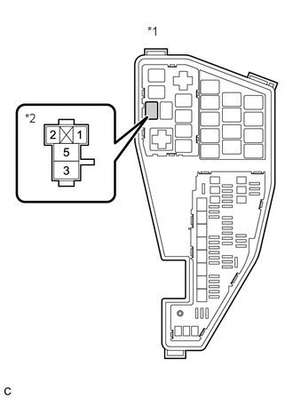
*1 No. 1 Engine Room Relay Block and No. 1 Junction Block Assembly *2 D INJ Relay - Remove the D INJ relay from the No. 1 engine room relay block and No. 1 junction block assembly.
- Measure the voltage according to the value(s) in the table below.
Standard Voltage
Tester Connection Condition Specified Condition 3 (D INJ relay) - Body ground Always 11 to 14 V Result
Proceed to OK NG
Result:
NG
REPAIR OR REPLACE HARNESS OR CONNECTOR (AUXILIARY BATTERY - D INJ RELAY)
Result:
OK
See step 6
- CHECK TERMINAL VOLTAGE (POWER SOURCE OF D INJ RELAY)
*1 No. 1 Engine Room Relay Block and No. 1 Junction Block Assembly *2 D INJ Relay - Remove the D INJ relay from the No. 1 engine room relay block and No. 1 junction block assembly.
- Turn the ignition switch to ON.
- Measure the voltage according to the value(s) in the table below.
Standard Voltage
Tester Connection Condition Specified Condition 1 (D INJ relay) - Body ground Ignition switch ON 11 to 14 V Result
Proceed to OK NG
Result:
NG
REPAIR OR REPLACE HARNESS OR CONNECTOR (EFI-MAIN NO. 1 RELAY - D INJ RELAY)
Result:
OK
See step 7
- CHECK HARNESS AND CONNECTOR (D INJ RELAY - ECM)
- Remove the D INJ relay from the No. 1 engine room relay block and No. 1 junction block assembly.
- Disconnect the ECM connector.
- Measure the resistance according to the value(s) in the table below.
Standard Resistance
Tester Connection Condition Specified Condition 5 (D INJ relay) - A27-53 (+BD1) Always Below 1 Ω 2 (D INJ relay) - A27-34 (IREL) Always Below 1 Ω 5 (D INJ relay) or A27-53 (+BD1) - Body ground and other terminals Always 10 kΩ or higher 2 (D INJ relay) or A27-34 (IREL) - Body ground and other terminals Always 10 kΩ or higher Result
Proceed to OK NG
Result:
OK
REPLACE ECM
Refer to REMOVAL [12/2019 - 10/2022]
Result:
NG
REPAIR OR REPLACE HARNESS OR CONNECTOR