DTC P0030-12: HO2S Heater Control Bank 1 Sensor 1 Circuit Short to Battery; DTC P0030-13: HO2S Heater Control Bank 1 Sensor 1 Circuit Open; DTC P101A-9E: A/F Sensor Heater Performance Bank 1 Sensor 1 Stuck On [10/2022 - 11/2023]: Procedure
- INSPECT AIR FUEL RATIO SENSOR (SENSOR 1) (HEATER RESISTANCE)
Refer to INSPECTION [12/2019 - ]
HINT:
Perform "Inspection After Repair" after replacing the air fuel ratio sensor (sensor 1).
Refer to INITIALIZATION [10/2021 - ]
Result
Proceed to OK NG Result:
NG
REPLACE AIR FUEL RATIO SENSOR (SENSOR 1)
Refer to REMOVAL [12/2019 - ]
Result:
OK
See step 2
- CHECK TERMINAL VOLTAGE (POWER SOURCE OF AIR FUEL RATIO SENSOR (SENSOR 1))
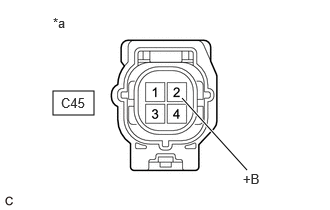
*a Front view of wire harness connector
(to Air Fuel Ratio Sensor (Sensor 1))- Disconnect the air fuel ratio sensor (sensor 1) connector.
- Turn the ignition switch to ON.
- Measure the voltage according to the value(s) in the table below.
Standard Voltage
Tester Connection Condition Specified Condition C45-2 (+B) - Body ground Ignition switch ON 11 to 14 V Result
Proceed to OK NG
Result:
NG
See step 6
Result:
OK
See step 3
- CHECK HARNESS AND CONNECTOR (AIR FUEL RATIO SENSOR (SENSOR 1) - ECM)
- Disconnect the air fuel ratio sensor (sensor 1) connector.
- Disconnect the ECM connector.
- Measure the resistance according to the value(s) in the table below.
Standard Resistance
Tester Connection Condition Specified Condition C45-1 (HA1A) - C55-9 (HA1A) Always Below 1 Ω C45-1 (HA1A) or C55-9 (HA1A) - Body ground and other terminals Always 10 kΩ or higher Result
Proceed to OK NG
Result:
NG
REPAIR OR REPLACE HARNESS OR CONNECTOR
Result:
OK
See step 4
- CLEAR DTC
- Clear the DTCs.
Powertrain > Engine > Clear DTCs
- Turn the ignition switch off and wait for at least 30 seconds.
Result
Proceed to NEXT
Result:
NEXT
See step 5
- Clear the DTCs.
- CHECK WHETHER DTC OUTPUT RECURS (DTC P0030-12, P0030-13 AND/OR P101A-9E)
- Drive the vehicle in accordance with the driving pattern described in Confirmation Driving Pattern.
- Read the DTCs.
Powertrain > Engine > Trouble Codes
Result
Result Proceed to DTCs are not output A DTC P0030-12, P0030-13 and/or P101A-9E is output B
Result:
A
CHECK FOR INTERMITTENT PROBLEMS
Refer to CHECK FOR INTERMITTENT PROBLEMS [12/2019 - ]
Result:
B
REPLACE ECM
Refer to REMOVAL [10/2022 - 11/2023]
- INSPECT EFI-MAIN NO. 2 RELAY
Refer to PROCEDURE - Step 2
Result
Proceed to OK NG Result:
NG
REPLACE EFI-MAIN NO. 2 RELAY
Result:
OK
See step 7
- CHECK TERMINAL VOLTAGE (POWER SOURCE OF EFI-MAIN NO. 2 RELAY)
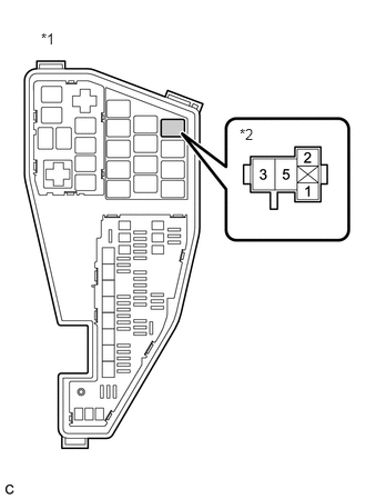
*1 No. 1 Engine Room Relay Block and No. 1 Junction Block Assembly *2 EFI-MAIN NO. 2 Relay - Remove the EFI-MAIN NO. 2 relay from the No. 1 engine room relay block and No. 1 junction block assembly.
- Measure the voltage according to the value(s) in the table below.
Standard Voltage
Tester Connection Condition Specified Condition 3 (EFI-MAIN NO. 2 relay) - Body ground Always 11 to 14 V Result
Proceed to OK NG
Result:
NG
REPAIR OR REPLACE HARNESS OR CONNECTOR (AUXILIARY BATTERY - EFI-MAIN NO. 2 RELAY)
Result:
OK
See step 8
- CHECK HARNESS AND CONNECTOR (EFI-MAIN NO. 2 RELAY - BODY GROUND)
- Remove the EFI-MAIN NO. 2 relay from the No. 1 engine room relay block and No. 1 junction block assembly.
- Measure the resistance according to the value(s) in the table below.
Standard Resistance
Tester Connection Condition Specified Condition 1 (EFI-MAIN NO. 2 relay) - Body ground Always Below 1 Ω Result
Proceed to OK NG
Result:
NG
REPAIR OR REPLACE HARNESS OR CONNECTOR
Result:
OK
See step 9
- CHECK HARNESS AND CONNECTOR (EFI-MAIN NO. 2 RELAY - AIR FUEL RATIO SENSOR (SENSOR 1))
- Remove the EFI-MAIN NO. 2 relay from the No. 1 engine room relay block and No. 1 junction block assembly.
- Disconnect the air fuel ratio sensor (sensor 1) connector.
- Measure the resistance according to the value(s) in the table below.
Standard Resistance
Tester Connection Condition Specified Condition 5 (EFI-MAIN NO. 2 relay) - C45-2 (+B) Always Below 1 Ω 5 (EFI-MAIN NO. 2 relay) or C45-2 (+B) - Body ground and other terminals Always 10 kΩ or higher Result
Proceed to OK NG
Result:
OK
REPAIR OR REPLACE HARNESS OR CONNECTOR (EFI-MAIN NO. 1 RELAY - EFI-MAIN NO. 2 RELAY)
Result:
NG
REPAIR OR REPLACE HARNESS OR CONNECTOR