DTC P274A-1C: Transmission Fluid Temperature Sensor "C" Voltage Out of Range; DTC P274A-1F: Transmission Fluid Temperature Sensor "C" Circuit Intermittent [12/2019 - 11/2023]: Procedure
- CHECK DTC OUTPUT (ENGINE)
- Check for DTCs.
Powertrain > Engine > Trouble Codes
Result
Result Proceed to No DTCs are output, or DTCs except the ones in the table below are also output. A Any of the following DTCs are also output. B Relevant DTC P2610-29 ECM/PCM Engine Off Timer Performance Signal Invalid - Turn the ignition switch off.
Result:
B
GO TO DTC CHART (SFI SYSTEM). Refer to DIAGNOSTIC TROUBLE CODE CHART [12/2019 - 09/2020] , or refer to DIAGNOSTIC TROUBLE CODE CHART [09/2020 - 10/2021] , or refer to DIAGNOSTIC TROUBLE CODE CHART [10/2021 - 10/2022] , or refer to DIAGNOSTIC TROUBLE CODE CHART [10/2022 - 11/2023]
Result:
A
See step 2
- Check for DTCs.
- CHECK DTC OUTPUT (HYBRID CONTROL)
- Check for DTCs.
Powertrain > Hybrid Control > Trouble Codes
Result
Result Proceed to No DTCs are output, or DTCs except the ones in the table below are also output. A Any of the following DTCs are also output. B Relevant DTC P274A-11 Transmission Fluid Temperature Sensor "C" Circuit Short to Ground P274A-15 Transmission Fluid Temperature Sensor "C" Circuit Short to Auxiliary Battery or Open - Turn the ignition switch off.
Result:
B
GO TO DTC CHART (HYBRID CONTROL SYSTEM). Refer to DIAGNOSTIC TROUBLE CODE CHART [12/2019 - 09/2020] , or refer to DIAGNOSTIC TROUBLE CODE CHART [09/2020 - 10/2021] , or refer to DIAGNOSTIC TROUBLE CODE CHART [10/2021 - 11/2023]
Result:
A
See step 3
- Check for DTCs.
- CHECK CONNECTOR CONNECTION CONDITION (HYBRID VEHICLE CONTROL ECU CONNECTOR)
Refer to PROCEDURE - Step 1
Result
Result Proceed to OK A NG (The connector is not connected securely.) B NG (The terminals are not making secure contact or are deformed, or water or foreign matter exists in the connector.) C Result:
B
CONNECT SECURELY
Result:
C
REPAIR OR REPLACE HARNESS OR CONNECTOR
Result:
A
See step 4
- CHECK HARNESS AND CONNECTOR (TRANSMISSION FLUID TEMPERATURE SENSOR - HYBRID VEHICLE CONTROL ECU)
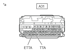
- Disconnect the A31 hybrid vehicle control ECU connector.
- Measure the resistance according to the value(s) in the table below.
*a Front view of wire harness connector
(to Hybrid Vehicle Control ECU)Standard Resistance
Tester Connection Condition Specified Condition A31-40 (TTA) - A31-39 (ETTA) Ignition switch off 1.4 to 94 kΩ - Reconnect the A31 hybrid vehicle control ECU connector.
Result
Proceed to OK NG
Result:
NG
See step 9
Result:
OK
See step 5
- CHECK CONNECTOR CONNECTION CONDITION (INTERMEDIATE CONNECTOR)
See step 2
Result
Result Proceed to OK A NG (The connector is not connected securely.) B NG (The terminals are not making secure contact or are deformed, or water or foreign matter exists in the connector.) C Result:
B
CONNECT SECURELY
Result:
C
REPAIR OR REPLACE HARNESS OR CONNECTOR
Result:
A
See step 6
- CHECK HARNESS AND CONNECTOR (HYBRID VEHICLE CONTROL ECU - NO. 1 ENGINE ROOM RELAY BLOCK AND NO. 1 JUNCTION BLOCK ASSEMBLY)
- Disconnect the CA2 No. 1 engine room relay block and No. 1 junction block assembly connector.
- Disconnect the A31 hybrid vehicle control ECU connector.
- Measure the resistance according to the value(s) in the table below.
HINT:
When performing the measurement, lightly jiggle the wire harness up and down and left and right and confirm that the resistance does not fluctuate.
Standard Resistance (Check for Open)
Tester Connection Condition Specified Condition CA2-5 (TTA) - A31-40 (TTA) Ignition switch off Below 1 Ω CA2-6 (ETTA) - A31-39 (ETTA) Ignition switch off Below 1 Ω Standard Resistance (Check for Short)
Tester Connection Condition Specified Condition CA2-5 (TTA) or A31-40 (TTA) - Body ground and other terminals Ignition switch off 10 kΩ or higher CA2-6 (ETTA) or A31-39 (ETTA) - Body ground and other terminals Ignition switch off 10 kΩ or higher - Reconnect the A31 hybrid vehicle control ECU connector.
- Reconnect the CA2 No. 1 engine room relay block and No. 1 junction block assembly connector.
Result
Proceed to OK NG
Result:
NG
REPAIR OR REPLACE HARNESS OR CONNECTOR
Result:
OK
See step 7
- CHECK CONNECTOR CONNECTION CONDITION (TRANSMISSION FLUID TEMPERATURE SENSOR CONNECTOR)
See step 3
Result
Result Proceed to OK A NG (The connector is not connected securely.) B NG (The terminals are not making secure contact or are deformed, or water or foreign matter exists in the connector.) C Result:
B
CONNECT SECURELY
Result:
C
REPAIR OR REPLACE HARNESS OR CONNECTOR
Result:
A
See step 8
- CHECK HARNESS AND CONNECTOR (NO. 1 ENGINE ROOM RELAY BLOCK AND NO. 1 JUNCTION BLOCK ASSEMBLY - TRANSMISSION FLUID TEMPERATURE SENSOR)
- Disconnect the C63 transmission fluid temperature sensor connector.
- Disconnect the CA2 No. 1 engine room relay block and No. 1 junction block assembly connector.
- Measure the resistance according to the value(s) in the table below.
Standard Resistance (Check for Open)
Tester Connection Condition Specified Condition CA2-5 (TTA) - C63-3 (TTA) Ignition switch off Below 1 Ω CA2-6 (ETTA) - C63-13 (ETTA) Ignition switch off Below 1 Ω Standard Resistance (Check for Short)
Tester Connection Condition Specified Condition CA2-5 (TTA) or C63-3 (TTA) - Body ground and other terminals Ignition switch off 10 kΩ or higher CA2-6 (ETTA) or C63-13 (ETTA) - Body ground and other terminals Ignition switch off 10 kΩ or higher - Reconnect the CA2 No. 1 engine room relay block and No. 1 junction block assembly connector.
- Reconnect the C63 transmission fluid temperature sensor connector.
Result
Proceed to OK NG
Result:
OK
REPLACE HYBRID VEHICLE TRANSAXLE ASSEMBLY. Refer to REMOVAL [12/2019 - 10/2022] , or refer to REMOVAL [10/2022 - 11/2023]
Result:
NG
REPAIR OR REPLACE HARNESS OR CONNECTOR
- INSPECT HYBRID VEHICLE TRANSAXLE ASSEMBLY (TRANSMISSION FLUID TEMPERATURE SENSOR)
- Disconnect the CA2 No. 1 engine room relay block and No. 1 junction block assembly connector.
- Measure the resistance according to the value(s) in the table below.
Standard Resistance
Tester Connection Condition Specified Condition CA2-5 (TTA) - CA2-6 (ETTA) Ignition switch off 1.4 to 94 kΩ - Reconnect the CA2 No. 1 engine room relay block and No. 1 junction block assembly connector.
Result
Proceed to OK NG
Result:
OK
REPAIR OR REPLACE HARNESS OR CONNECTOR (HYBRID VEHICLE CONTROL ECU - NO. 1 ENGINE ROOM RELAY BLOCK AND NO. 1 JUNCTION BLOCK ASSEMBLY)
Result:
NG
See step 10
- INSPECT HYBRID VEHICLE TRANSAXLE ASSEMBLY (TRANSMISSION FLUID TEMPERATURE SENSOR)
See step 7
Result
Proceed to OK NG Result:
OK
REPAIR OR REPLACE HARNESS OR CONNECTOR (NO. 1 ENGINE ROOM RELAY BLOCK AND NO. 1 JUNCTION BLOCK ASSEMBLY - TRANSMISSION FLUID TEMPERATURE SENSOR)
Result:
NG
REPLACE HYBRID VEHICLE TRANSAXLE ASSEMBLY. Refer to REMOVAL [12/2019 - 10/2022] , or refer to REMOVAL [10/2022 - 11/2023]