DTC P3123-87: Lost Communication with Drive Motor Control Module "A" from Hybrid/EV Control Module Missing Message [12/2019 - 11/2023]: Procedure
- INSPECT FUSE (PCU)
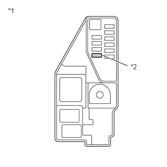
- Remove the PCU fuse from the No. 5 floor relay block and No. 5 floor junction block assembly.
- Measure the resistance according to the value(s) in the table below.
*1 No. 5 Floor Relay Block and No. 5 Floor Junction Block Assembly *2 PCU Fuse Standard Resistance
Tester Connection Condition Specified Condition PCU fuse Always Below 1 Ω - Install the PCU fuse.
Result
Proceed to OK NG
Result:
NG
See step 9
Result:
OK
See step 2
- CLEAR DTC
Refer to PROCEDURE - Step 3
Result
Proceed to NEXT Result:
NEXT
See step 3
- CHECK DIAGNOSIS RELATED INFORMATION AND DTC OUTPUT (HYBRID CONTROL)
- Turn the ignition switch to ON and wait for 2 minutes or more.
- Check for Diagnosis Related Information and DTCs.
Powertrain > Hybrid Control > Utility
Tester Display Diagnosis Related Information Powertrain > Hybrid Control > Trouble Codes
Result
Result Proceed to P3123-87 is listed in Diagnosis Related Information or DTC P3123-87 is output. A P3123-87 is not listed in Diagnosis Information and DTC P3123-87 is not output. B - Turn the ignition switch off.
Result:
B
CHECK FOR INTERMITTENT PROBLEMS
Refer to CHECK FOR INTERMITTENT PROBLEMS [12/2019 - 11/2023]
Result:
A
See step 4
- CHECK CONNECTOR CONNECTION CONDITION (HYBRID VEHICLE CONTROL ECU CONNECTOR)
Refer to PROCEDURE - Step 1
Result
Proceed to OK NG Result:
NG
CONNECT SECURELY
Result:
OK
See step 5
- CHECK CONNECTOR CONNECTION CONDITION (INVERTER WITH CONVERTER ASSEMBLY CONNECTOR)
Refer to PROCEDURE - Step 3
Result
Result Proceed to OK A NG (The connector is not connected securely.) B NG (The terminals are not making secure contact or are deformed, or water or foreign matter exists in the connector.) C Result:
B
CONNECT SECURELY
Result:
C
REPAIR OR REPLACE HARNESS OR CONNECTOR
Result:
A
See step 6
- CHECK HARNESS AND CONNECTOR (INVERTER WITH CONVERTER ASSEMBLY POWER SOURCE CIRCUIT) WARNING:
Be sure to wear insulated gloves.
- Check that the service plug grip is not installed.NOTE:
After removing the service plug grip, do not turn the ignition switch to ON (READY), unless instructed by the repair information because this may cause a malfunction.
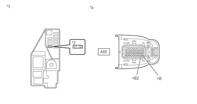
- Disconnect the A55 inverter with converter assembly connector.
Refer to REMOVAL [12/2019 - 10/2022] , or refer to REMOVAL [10/2022 - 11/2023]
- Measure the resistance according to the value(s) in the table below.
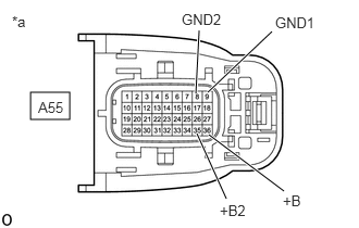
*a Front view of wire harness connector
(to Inverter with Converter Assembly)Standard Resistance
Tester Connection Condition Specified Condition A55-9 (GND1) - Body ground Ignition switch off Below 1 Ω A55-8 (GND2) - Body ground Ignition switch off Below 1 Ω - Connect the cable to the negative (-) auxiliary battery terminal.
- Turn the ignition switch to ON.
- Measure the voltage according to the value(s) in the table below.
Standard Voltage
Tester Connection Condition Specified Condition A55-36 (+B) - Body ground Ignition switch ON 11 to 14 V A55-35 (+B2) - Body ground Ignition switch ON 11 to 14 V NOTE:Turning the ignition switch to ON with the inverter with converter assembly disconnected causes other DTCs to be stored. Clear the DTCs after performing this inspection.
- Turn the ignition switch off.
- Disconnect the cable from the negative (-) auxiliary battery terminal.
- Reconnect the A55 inverter with converter assembly connector.
Result
Proceed to OK NG
Result:
NG
REPAIR OR REPLACE HARNESS OR CONNECTOR
Result:
OK
See step 7
- Check that the service plug grip is not installed.
- CHECK HARNESS AND CONNECTOR (INVERTER WITH CONVERTER ASSEMBLY - HYBRID VEHICLE CONTROL ECU) WARNING:
Be sure to wear insulated gloves.
- Check that the service plug grip is not installed.NOTE:
After removing the service plug grip, do not turn the ignition switch to ON (READY), unless instructed by the repair information because this may cause a malfunction.
- Disconnect the A55 inverter with converter assembly connector.
- Disconnect the A31 hybrid vehicle control ECU connector.
- Connect the cable to the negative (-) auxiliary battery terminal.
- Turn the ignition switch to ON.
- Measure the voltage according to the value(s) in the table below.
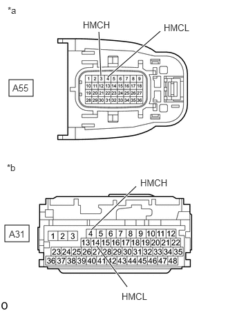
*a Front view of wire harness connector
(to Inverter with Converter Assembly)*b Front view of wire harness connector
(to Hybrid Vehicle Control ECU)Standard Voltage
Tester Connection Condition Specified Condition A31-14 (HMCL) - Body ground Ignition switch ON Below 1 V A31-4 (HMCH) - Body ground Ignition switch ON Below 1 V NOTE:Turning the ignition switch to ON with the hybrid vehicle control ECU connector and the inverter with converter assembly disconnected causes other DTCs to be stored. Clear the DTCs after performing this inspection.
- Turn the ignition switch off.
- Disconnect the cable from the negative (-) auxiliary battery terminal.
- Measure the resistance according to the value(s) in the table below.
Standard Resistance (Check for Open)
Tester Connection Condition Specified Condition A55-4 (HMCL) - A31-14 (HMCL) Ignition switch off Below 1 Ω A55-3 (HMCH) - A31-4 (HMCH) Ignition switch off Below 1 Ω Standard Resistance (Check for Short)
Tester Connection Condition Specified Condition A55-4 (HMCL) or A31-14 (HMCL) - Body ground and other terminals Ignition switch off 10 kΩ or higher A55-3 (HMCH) or A31-4 (HMCH) - Body ground and other terminals Ignition switch off 10 kΩ or higher HINT:
As there might be an intermittent malfunction, inspect the following items even if the measured resistance is as specified.
Check that each connector between the inverter with converter assembly and hybrid vehicle control ECU is not loose or disconnected.
- Reconnect the A31 hybrid vehicle control ECU connector.
- Reconnect the A55 inverter with converter assembly connector.
Result
Proceed to OK NG
Result:
NG
REPAIR OR REPLACE HARNESS OR CONNECTOR
Result:
OK
See step 8
- Check that the service plug grip is not installed.
- CHECK HYBRID VEHICLE CONTROL ECU WARNING:
Be sure to wear insulated gloves.
- Check that the service plug grip is not installed.NOTE:
After removing the service plug grip, do not turn the ignition switch to ON (READY), unless instructed by the repair information because this may cause a malfunction.
- Disconnect the A55 inverter with converter assembly connector.
- Measure the resistance according to the value(s) in the table below.
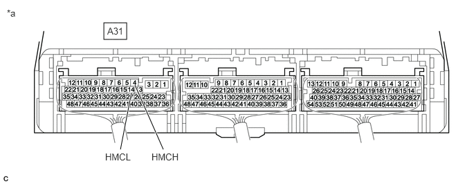
*a Component with harness connected
(Hybrid Vehicle Control ECU)- - Standard Resistance
Tester Connection Condition Specified Condition A31-14 (HMCL) - A31-4 (HMCH) Ignition switch off 110 to 130 Ω - Reconnect the A55 inverter with converter assembly connector.
Result
Proceed to OK NG
Result:
OK
REPLACE INVERTER WITH CONVERTER ASSEMBLY
Refer to REMOVAL [12/2019 - 10/2022] , or refer to REMOVAL [10/2022 - 11/2023]
Result:
NG
REPLACE HYBRID VEHICLE CONTROL ECU
Refer to REMOVAL [12/2019 - 10/2022] , or refer to REMOVAL [10/2022 - 11/2023]
- Check that the service plug grip is not installed.
- REPLACE FUSE (PCU)
- Replace the PCU fuse.
*1 No. 5 Floor Relay Block and No. 5 Floor Junction Block Assembly *2 PCU Fuse - Turn the ignition switch to ON (READY).
- Check if there is an open circuit in the PCU fuse in the No. 5 floor relay block and No. 5 floor junction block assembly.
OK
There is no open circuit in the PCU fuse.
HINT:
If the fuse does not become open again after turning the ignition switch to ON (READY), it can be assumed that the previous fuse failed due to age.
- Turn the ignition switch off.
Result
Proceed to OK NG
Result:
OK
END
Result:
NG
See step 10
- Replace the PCU fuse.
- CHECK HARNESS AND CONNECTOR (INVERTER WITH CONVERTER ASSEMBLY - PCU FUSE) WARNING:
Be sure to wear insulated gloves.
- Check that the service plug grip is not installed.NOTE:
After removing the service plug grip, do not turn the ignition switch to ON (READY), unless instructed by the repair information because this may cause a malfunction.
- Remove the PCU fuse from the No. 5 floor relay block and No. 5 floor junction block assembly.
- Disconnect the A55 inverter with converter assembly connector.
- Measure the resistance according to the value(s) in the table below.
*1 No. 5 Floor Relay Block and No. 5 Floor Junction Block Assembly *2 PCU Fuse Holder *a Front view of wire harness connector
(to Inverter with Converter Assembly)- - Standard Resistance (Check for Short)
Tester Connection Condition Specified Condition A55-36 (+B), A55-35 (+B2) or 2 (PCU fuse holder) - Body ground and other terminals Ignition switch off 10 kΩ or higher - Reconnect the A55 inverter with converter assembly connector.
- Install the PCU fuse.
Result
Proceed to OK NG
Result:
NG
See step 12
Result:
OK
See step 11
- Check that the service plug grip is not installed.
- REPLACE INVERTER WITH CONVERTER ASSEMBLY
Refer to REMOVAL [12/2019 - 10/2022] , or refer to REMOVAL [10/2022 - 11/2023]
Result
Proceed to NEXT Result:
NEXT
REPLACE FUSE (PCU)
- REPAIR OR REPLACE HARNESS OR CONNECTOR
Result
Proceed to NEXT Result:
NEXT
REPLACE FUSE (PCU)