DTC P314A-31: Motor Electronics Coolant Pump "A" No Signal [12/2019 - 11/2023]: Procedure
- CLEAR DTC
- Read and record the DTCs and Freeze Frame Data.
Powertrain > Hybrid Control > Trouble Codes
- Clear the DTCs and Freeze Frame Data.
Powertrain > Hybrid Control > Clear DTCs
- Turn the ignition switch off and wait for 2 minutes or more.
Result
Proceed to NEXT
Result:
NEXT
See step 2
- Read and record the DTCs and Freeze Frame Data.
- PERFORM ACTIVE TEST USING GTS (ACTIVATE THE INVERTER WATER PUMP) NOTE:
- Make sure that the HV coolant level is above the low line of the inverter reserve tank.
- Be sure to perform the inspection with the auxiliary battery voltage at 12 V or more.
HINT:
- When the auxiliary battery voltage is low, the inverter water pump assembly may not operate.
- When the inverter water pump assembly signal line (SWP - IWP) is open or its connection is faulty, the inverter water pump assembly is operated forcibly.
- Perform the "Activate the Inverter Water Pump" Active Test.
Powertrain > Hybrid Control > Active Test
Tester Display Activate the Inverter Water Pump - Touch the inverter water pump assembly and check that it is operating (vibrating).
OK
The inverter water pump is operating (vibrating).
HINT:
Perform the Active Test with the inverter coolant temperature between -15 and 65°C (5 to 149°F).
- Turn the ignition switch off.
Result
Proceed to OK NG
Result:
NG
See step 9
Result:
OK
See step 3
- CHECK CONNECTOR CONNECTION CONDITION (HYBRID VEHICLE CONTROL ECU CONNECTOR)
Refer to PROCEDURE - Step 1
Result
Proceed to OK NG Result:
NG
CONNECT SECURELY
Result:
OK
See step 4
- CHECK CONNECTOR CONNECTION CONDITION (INVERTER WATER PUMP ASSEMBLY CONNECTOR)
Refer to PROCEDURE - Step 10 [12/2019 - 10/2021] , or refer to PROCEDURE - Step 10 [10/2021 - 11/2023]
Result
Proceed to OK NG Result:
NG
CONNECT SECURELY
Result:
OK
See step 5
- CHECK HARNESS AND CONNECTOR (HYBRID VEHICLE CONTROL ECU - INVERTER WATER PUMP ASSEMBLY)
- Disconnect the A31 hybrid vehicle control ECU connector.
- Disconnect the A56 inverter water pump assembly connector.
- Measure the resistance according to the value(s) in the table below.
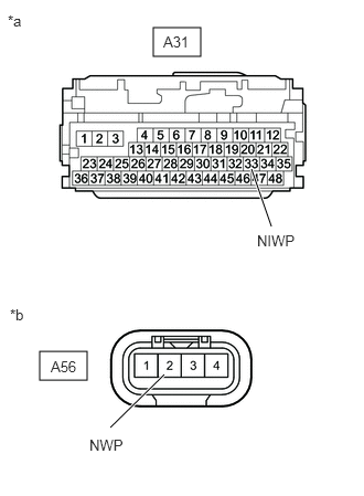
*a Front view of wire harness connector
(to Hybrid Vehicle Control ECU)*b Front view of wire harness connector
(to Inverter Water Pump Assembly)Standard Resistance (Check for Open)
Tester Connection Condition Specified Condition A31-33 (NIWP) - A56-2 (NWP) Ignition switch off Below 1 Ω Standard Resistance (Check for Short)
Tester Connection Condition Specified Condition A31-33 (NIWP) or A56-2 (NWP) - Body ground and other terminals Ignition switch off 10 kΩ or higher HINT:
Check the condition (looseness, deterioration, etc.) of the wire to body ground for the inverter water pump assembly.
- Reconnect the A56 inverter water pump assembly connector.
- Reconnect the A31 hybrid vehicle control ECU connector.
Result
Proceed to OK NG
Result:
NG
REPAIR OR REPLACE HARNESS OR CONNECTOR
Result:
OK
See step 6
- CHECK HYBRID VEHICLE CONTROL ECU
- Disconnect the A56 inverter water pump assembly connector.
- Turn the ignition switch to ON.
- Measure the voltage according to the value(s) in the table below.
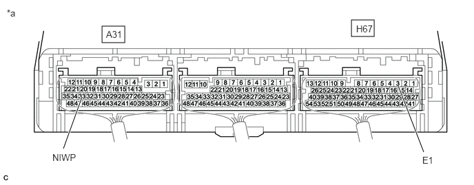
*a Component with harness connected
(Hybrid Vehicle Control ECU)- - Standard Voltage
Tester Connection Condition Specified Condition A31-33 (NIWP) - H67-3 (E1) Ignition switch ON 11 to 14 V - Turn the ignition switch off.
- Reconnect the A56 inverter water pump assembly connector.
Result
Proceed to OK NG
Result:
NG
REPLACE HYBRID VEHICLE CONTROL ECU
Refer to REMOVAL [12/2019 - 10/2022] , or refer to REMOVAL [10/2022 - 11/2023]
Result:
OK
See step 7
- CLEAR DTC
Refer to PROCEDURE - Step 3
Result
Proceed to NEXT Result:
NEXT
See step 8
- PERFORM ACTIVE TEST USING GTS (ACTIVATE THE INVERTER WATER PUMP) NOTE:
Be sure to perform the inspection with the auxiliary battery voltage at 12 V or more.
HINT:
When the auxiliary battery voltage is low, the inverter water pump assembly may not operate.
- Perform the "Activate the Inverter Water Pump" Active Test.
Powertrain > Hybrid Control > Active Test
Tester Display Activate the Inverter Water Pump - Connect an oscilloscope between the hybrid vehicle control ECU terminals specified in the table below, and measure the waveform.
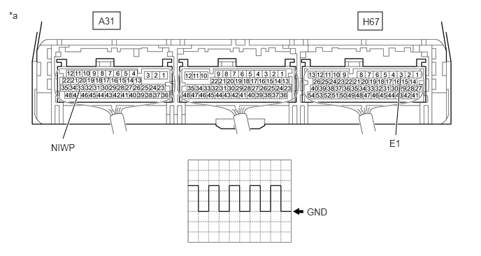
*a Component with harness connected
(Hybrid Vehicle Control ECU)- - Item Content Terminal A31-33 (NIWP) - H67-3 (E1) Equipment Setting 5 V/DIV., 5 ms./DIV. Condition Ignition switch ON, during Active Test OK
The period of the wavelength is 13 msec or less.
- Turn the ignition switch off.
Result
Proceed to OK NG
Result:
OK
REPLACE HYBRID VEHICLE CONTROL ECU
Refer to REMOVAL [12/2019 - 10/2022] , or refer to REMOVAL [10/2022 - 11/2023]
Result:
NG
See step 15
- Perform the "Activate the Inverter Water Pump" Active Test.
- CHECK CONNECTOR CONNECTION CONDITION (INVERTER WATER PUMP ASSEMBLY CONNECTOR)
Refer to PROCEDURE - Step 10 [12/2019 - 10/2021] , or refer to PROCEDURE - Step 10 [10/2021 - 11/2023]
Result
Proceed to OK NG Result:
NG
CONNECT SECURELY (INVERTER WATER PUMP ASSEMBLY CONNECTOR)
Result:
OK
See step 10
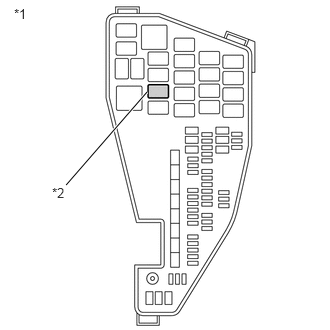
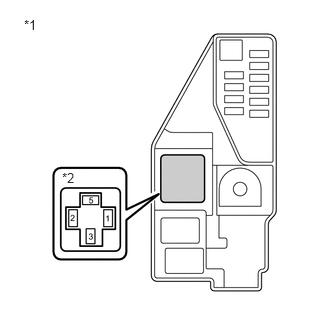
- CHECK INSTALLATION CONDITION (INV W/PMP RELAY)
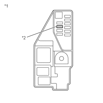
- Check installation condition of the INV W/PMP relay.
*1 No. 1 Engine Room Relay Block and No. 1 Junction Block Assembly *2 INV W/PMP Relay OK
INV W/PMP relay is installed correctly.
Result
Proceed to OK NG
Result:
NG
See step 17
Result:
OK
See step 11
- Check installation condition of the INV W/PMP relay.
- CHECK HARNESS AND CONNECTOR (IGCT RELAY - INV W/PMP RELAY)
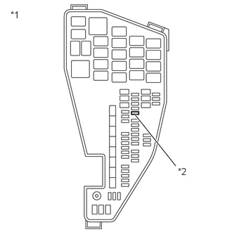
- Remove the IGCT relay from the No. 5 floor relay block and No. 5 floor junction block assembly.
*1 No. 5 Floor Relay Block and No. 5 Floor Junction Block Assembly *2 IGCT Relay Holder - Remove the INV W/PMP relay from the No. 1 engine room relay block and No. 1 junction block assembly.
*1 No. 1 Engine Room Relay Block and No. 1 Junction Block Assembly *2 INV W/PMP Relay Holder - Measure the resistance according to the value(s) in the table below.
Standard Resistance
Tester Connection Condition Specified Condition 5 (IGCT relay holder) - 1 (INV W/PMP relay holder) Ignition switch off Below 1 Ω NOTE:Do not apply excessive force when using the probes of the tester to perform the inspection. If excessive force is used, the terminals will be damaged.
HINT:
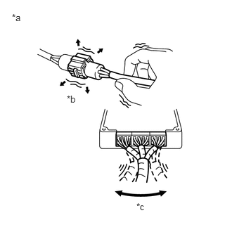
- Connectors
Slightly shake the connector vertically and horizontally.
- Wire Harness
Slightly shake the wire harness vertically and horizontally.
The connector joint and fulcrum of the vibration are the major areas that should be checked thoroughly.
- No. 5 Floor Relay Block and No. 5 Floor Junction Block Assembly
Apply slight vibration with a finger to the No. 5 floor relay block and No. 5 floor junction block assembly and check whether a malfunction occurs.
- No. 1 Engine Room Relay Block and No. 1 Junction Block Assembly
Apply slight vibration with a finger to the No. 1 engine room relay block and No. 1 junction block assembly and check whether a malfunction occurs.
- IGCT NO. 2 fuse
Apply slight vibration with a finger to the IGCT NO. 2 fuse and check whether a malfunction occurs.
*a Example *b Shake Slightly *c Vibrate Slightly - Connectors
- Install the IGCT relay and INV W/PMP relay.
Result
Proceed to OK NG
Result:
NG
See step 18
Result:
OK
See step 12
- Remove the IGCT relay from the No. 5 floor relay block and No. 5 floor junction block assembly.
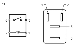
- INSPECT RELAY (INV W/PMP)
- Remove the INV W/PMP relay from the No. 1 engine room relay block and No. 1 junction block assembly.
*1 No. 1 Engine Room Relay Block and No. 1 Junction Block Assembly *2 INV W/PMP Relay - Measure the resistance according to the value(s) in the table below.
Standard Resistance
Tester Connection Condition Specified Condition 3 - 5 Auxiliary battery voltage not applied between terminals 1 and 2 10 kΩ or higher Auxiliary battery voltage applied between terminals 1 and 2 Below 1 Ω *1 INV W/PMP Relay - Install the INV W/PMP relay.
Result
Proceed to OK NG
Result:
NG
See step 20
Result:
OK
See step 13
- Remove the INV W/PMP relay from the No. 1 engine room relay block and No. 1 junction block assembly.
- CHECK HARNESS AND CONNECTOR (INVERTER WATER PUMP ASSEMBLY - BODY GROUND)
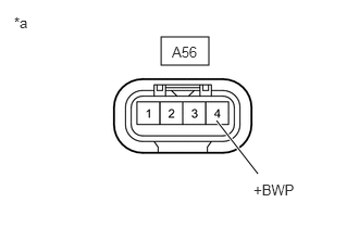
*a Front view of wire harness connector
(to Inverter Water Pump Assembly)*a Example *b Shake Slightly *c Vibrate Slightly - Disconnect the A56 inverter water pump assembly connector.
- Turn the ignition switch to ON.
- Measure the voltage according to the value(s) in the table below.
Standard Voltage
Tester Connection Condition Specified Condition A56-4 (+BWP) - Body ground Ignition switch ON 11 to 14 V NOTE:- If the ignition switch is turned to ON with the connectors disconnected, other DTCs will be stored. Be sure to clear the DTCs after the inspection.
- Do not apply excessive force when using the probes of the tester to perform the inspection. If excessive force is used, the terminals will be damaged.
HINT:
- Connectors
Slightly shake the connector vertically and horizontally.
- Wire Harness
Slightly shake the wire harness vertically and horizontally.
The connector joint and fulcrum of the vibration are the major areas that should be checked thoroughly.
- No. 1 Engine Room Relay Block and No. 1 Junction Block Assembly
Apply slight vibration with a finger to the No. 1 engine room relay block and No. 1 junction block assembly and check whether a malfunction occurs.
- INV W/PMP fuse
Apply slight vibration with a finger to the INV W/PMP fuse and check whether a malfunction occurs.
- INV W/PMP Relay
Apply slight vibration with a finger to the INV W/PMP relay and check whether a malfunction occurs.
- Turn the ignition switch off.
- Reconnect the A56 inverter water pump assembly connector.
Result
Proceed to OK NG
Result:
NG
See step 21
Result:
OK
See step 14
- CHECK HARNESS AND CONNECTOR (INVERTER WATER PUMP ASSEMBLY - BODY GROUND)
- Disconnect the A56 inverter water pump assembly connector.
- Measure the resistance according to the value(s) in the table below.
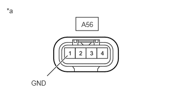
*a Front view of wire harness connector
(to Inverter Water Pump Assembly)Standard Resistance
Tester Connection Condition Specified Condition A56-1 (GND) - Body ground Ignition switch off Below 1 Ω - Reconnect the A56 inverter water pump assembly connector.
Result
Proceed to OK NG
Result:
NG
REPAIR OR REPLACE HARNESS OR CONNECTOR
Result:
OK
See step 15
- REPLACE INVERTER WATER PUMP ASSEMBLY
Refer to REMOVAL [12/2019 - ]
Result
Proceed to NEXT Result:
NEXT
See step 16
- ADD HV COOLANT AND PERFORM AIR BLEEDING
- After replacing the inverter water pump assembly, add HV coolant and perform air bleeding.
Refer to REPLACEMENT [12/2019 - ]
Result
Proceed to NEXT
Result:
NEXT
END
- After replacing the inverter water pump assembly, add HV coolant and perform air bleeding.
- INSPECT RELAY (INV W/PMP)
- Remove the INV W/PMP relay from the No. 1 engine room relay block and No. 1 junction block assembly.
*1 No. 1 Engine Room Relay Block and No. 1 Junction Block Assembly *2 INV W/PMP Relay - Measure the resistance according to the value(s) in the table below.
Standard Resistance
Tester Connection Condition Specified Condition 3 - 5 Auxiliary battery voltage not applied between terminals 1 and 2 10 kΩ or higher Auxiliary battery voltage applied between terminals 1 and 2 Below 1 Ω *1 INV W/PMP Relay - Install the INV W/PMP relay.
Result
Proceed to OK NG
Result:
OK
CONNECT SECURELY (INV W/PMP RELAY)
Result:
NG
REPLACE RELAY (INV W/PMP)
- Remove the INV W/PMP relay from the No. 1 engine room relay block and No. 1 junction block assembly.
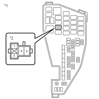
- CHECK INSTALLATION CONDITION (IGCT NO. 2 FUSE)
- Check installation condition of the IGCT NO. 2 fuse.
*1 No. 5 Floor Relay Block and No. 5 Floor Junction Block Assembly *2 IGCT NO. 2 Fuse OK
IGCT NO. 2 fuse is installed correctly.
Result
Proceed to OK NG
Result:
NG
See step 25
Result:
OK
See step 19
- Check installation condition of the IGCT NO. 2 fuse.
- CHECK FUSE (IGCT NO. 2)
- Remove the IGCT NO. 2 fuse from the No. 5 floor relay block and No. 5 floor junction block assembly.
*1 No. 5 Floor Relay Block and No. 5 Floor Junction Block Assembly *2 IGCT NO. 2 Fuse - Measure the resistance according to the value(s) in the table below.
Standard Resistance
Tester Connection Condition Specified Condition IGCT NO. 2 fuse Always Below 1 Ω - Install the IGCT NO. 2 fuse.
Result
Proceed to OK NG
Result:
OK
REPAIR OR REPLACE HARNESS OR CONNECTOR (IGCT NO. 2 FUSE HOLDER TERMINAL)
Result:
NG
See step 26
- Remove the IGCT NO. 2 fuse from the No. 5 floor relay block and No. 5 floor junction block assembly.
- CHECK RELAY HOLDER TERMINAL (INV W/PMP RELAY)
- Check the terminals of the INV W/PMP relay holder.
OK
The terminals of the INV W/PMP relay holder are not bent, loose or corroded.
*1 No. 1 Engine Room Relay Block and No. 1 Junction Block Assembly *2 INV W/PMP Relay Result
Proceed to OK NG
Result:
OK
REPLACE RELAY (INV W/PMP)
Result:
NG
See step 27
- Check the terminals of the INV W/PMP relay holder.
- CHECK INSTALLATION CONDITION (INV W/PMP FUSE)
- Check installation condition of the INV W/PMP fuse.
OK
INV W/PMP fuse is installed correctly.
*1 No. 1 Engine Room Relay Block and No. 1 Junction Block Assembly *2 INV W/PMP Fuse Result
Proceed to OK NG
Result:
NG
CONNECT SECURELY (INV W/PMP FUSE)
Result:
OK
See step 22
- Check installation condition of the INV W/PMP fuse.
- INSPECT RELAY (INV W/PMP)
- Remove the INV W/PMP relay from the No. 1 engine room relay block and No. 1 junction block assembly.
*1 No. 1 Engine Room Relay Block and No. 1 Junction Block Assembly *2 INV W/PMP Relay - Measure the resistance according to the value(s) in the table below.
Standard Resistance
Tester Connection Condition Specified Condition 3 - 5 Auxiliary battery voltage not applied between terminals 1 and 2 10 kΩ or higher Auxiliary battery voltage applied between terminals 1 and 2 Below 1 Ω *1 INV W/PMP Relay - Install the INV W/PMP relay.
Result
Proceed to OK NG
Result:
NG
See step 32
Result:
OK
See step 23
- Remove the INV W/PMP relay from the No. 1 engine room relay block and No. 1 junction block assembly.
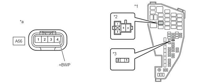
- CHECK HARNESS AND CONNECTOR (INVERTER WATER PUMP ASSEMBLY CIRCUIT)
- Remove the INV W/PMP relay and INV W/PMP fuse from the No. 1 engine room relay block and No. 1 junction block assembly.
- Disconnect the A56 inverter water pump assembly connector.
- Measure the resistance according to the value(s) in the table below.
*1 No. 1 Engine Room Relay Block and No. 1 Junction Block Assembly *2 INV W/PMP Relay Holder *3 INV W/PMP Fuse - - *a Front view of wire harness connector
(to Inverter Water Pump Assembly)- - Standard Resistance
Tester Connection Condition Specified Condition A56-4 (+BWP) - 3 (INV W/PMP relay holder) Ignition switch off Below 1 Ω 2 (INV W/PMP fuse holder) or A56-4 (+BWP) - Body ground and other terminals Ignition switch off 10 kΩ or higher NOTE:Do not apply excessive force when using the probes of the tester to perform the inspection. If excessive force is used, the terminals will be damaged.
- Reconnect the A56 inverter water pump assembly connector.
- Install the INV W/PMP relay and INV W/PMP fuse.
Result
Proceed to OK NG
Result:
NG
REPAIR OR REPLACE HARNESS OR CONNECTOR
Result:
OK
See step 24
- CHECK FUSE (INV W/PMP)
- Remove the INV W/PMP fuse from the No. 1 engine room relay block and No. 1 junction block assembly.
*1 No. 1 Engine Room Relay Block and No. 1 Junction Block Assembly *2 INV W/PMP Fuse - Measure the resistance according to the value(s) in the table below.
Standard Resistance
Tester Connection Condition Specified Condition INV W/PMP fuse Always Below 1 Ω - Install the INV W/PMP fuse.
Result
Proceed to OK NG
Result:
OK
REPAIR OR REPLACE HARNESS OR CONNECTOR (INV W/PMP FUSE HOLDER TERMINAL OR INV W/PMP RELAY HOLDER TERMINAL)
Result:
NG
See step 28
- Remove the INV W/PMP fuse from the No. 1 engine room relay block and No. 1 junction block assembly.
- INSPECT RELAY (INV W/PMP)
- Remove the INV W/PMP relay from the No. 1 engine room relay block and No. 1 junction block assembly.
*1 No. 1 Engine Room Relay Block and No. 1 Junction Block Assembly *2 INV W/PMP Relay - Measure the resistance according to the value(s) in the table below.
Standard Resistance
Tester Connection Condition Specified Condition 3 - 5 Auxiliary battery voltage not applied between terminals 1 and 2 10 kΩ or higher Auxiliary battery voltage applied between terminals 1 and 2 Below 1 Ω *1 INV W/PMP Relay - Install the INV W/PMP relay.
Result
Proceed to OK NG
Result:
OK
CONNECT SECURELY (IGCT NO. 2 FUSE)
Result:
NG
See step 30
- Remove the INV W/PMP relay from the No. 1 engine room relay block and No. 1 junction block assembly.
- CHECK FUSE HOLDER TERMINAL (IGCT NO. 2 FUSE)
- Check the terminals of the IGCT NO. 2 fuse holder.
*1 No. 5 Floor Relay Block and No. 5 Floor Junction Block Assembly *2 IGCT NO. 2 Fuse OK
The terminals of the IGCT NO. 2 fuse holder are not bent, loose or corroded.
Result
Proceed to OK NG
Result:
OK
REPLACE FUSE (IGCT NO. 2)
Result:
NG
See step 31
- Check the terminals of the IGCT NO. 2 fuse holder.
- REPAIR OR REPLACE HARNESS OR CONNECTOR (INV W/PMP RELAY HOLDER TERMINAL)
Result:
NEXT
REPLACE RELAY (INV W/PMP)
- REPLACE INVERTER WATER PUMP ASSEMBLY
Refer to REMOVAL [12/2019 - ]
Result
Proceed to NEXT Result:
NEXT
See step 29
- ADD HV COOLANT AND PERFORM AIR BLEEDING
- After replacing the inverter water pump assembly, add HV coolant and perform air bleeding.
Refer to REPLACEMENT [12/2019 - ]
Result
Proceed to NEXT
Result:
NEXT
REPLACE FUSE (INV W/PMP)
- After replacing the inverter water pump assembly, add HV coolant and perform air bleeding.
- REPLACE RELAY (INV W/PMP)
Result
Proceed to NEXT Result:
NEXT
CONNECT SECURELY (IGCT NO. 2 FUSE)
- REPAIR OR REPLACE HARNESS OR CONNECTOR (IGCT NO. 2 FUSE HOLDER TERMINAL)
Result:
NEXT
REPLACE FUSE (IGCT NO. 2)
- CHECK RELAY HOLDER TERMINAL (INV W/PMP RELAY)
- Check the terminals of the INV W/PMP relay holder.
OK
The terminals of the INV W/PMP relay holder are not bent, loose or corroded.
*1 No. 1 Engine Room Relay Block and No. 1 Junction Block Assembly *2 INV W/PMP Relay Result
Proceed to OK NG
Result:
NG
See step 34
Result:
OK
See step 33
- Check the terminals of the INV W/PMP relay holder.
- CHECK FUSE (IGCT NO. 2)
- Remove the IGCT NO. 2 fuse from the No. 5 floor relay block and No. 5 floor junction block assembly.
*1 No. 5 Floor Relay Block and No. 5 Floor Junction Block Assembly *2 IGCT NO. 2 Fuse - Measure the resistance according to the value(s) in the table below.
Standard Resistance
Tester Connection Condition Specified Condition IGCT NO. 2 fuse Always Below 1 Ω - Install the IGCT NO. 2 fuse.
Result
Proceed to OK NG
Result:
OK
REPLACE RELAY (INV W/PMP)
Result:
NG
See step 36
- Remove the IGCT NO. 2 fuse from the No. 5 floor relay block and No. 5 floor junction block assembly.
- CHECK FUSE (IGCT NO. 2)
- Remove the IGCT NO. 2 fuse from the No. 5 floor relay block and No. 5 floor junction block assembly.
*1 No. 5 Floor Relay Block and No. 5 Floor Junction Block Assembly *2 IGCT NO. 2 Fuse - Measure the resistance according to the value(s) in the table below.
Standard Resistance
Tester Connection Condition Specified Condition IGCT NO. 2 fuse Always Below 1 Ω - Install the IGCT NO. 2 fuse.
Result
Proceed to OK NG
Result:
NG
See step 37
Result:
OK
See step 35
- Remove the IGCT NO. 2 fuse from the No. 5 floor relay block and No. 5 floor junction block assembly.
- REPAIR OR REPLACE HARNESS OR CONNECTOR (INV W/PMP RELAY HOLDER TERMINAL)
Result:
NEXT
REPLACE RELAY (INV W/PMP)
- REPLACE RELAY (INV W/PMP)
Result
Proceed to NEXT Result:
NEXT
REPLACE FUSE (IGCT NO. 2)
- REPAIR OR REPLACE HARNESS OR CONNECTOR (INV W/PMP RELAY HOLDER TERMINAL)
Result:
NEXT
See step 38
- REPLACE RELAY (INV W/PMP)
Result
Proceed to NEXT Result:
NEXT
REPLACE FUSE (IGCT NO. 2)