DTC P1CE2-13: PCU Interlock Circuit Open; DTC P1CE2-92: PCU Interlock Performance or Incorrect Operation [12/2019 - 11/2023]: Procedure
- CHECK DTC OUTPUT (HYBRID CONTROL, MOTOR GENERATOR)
- Check for DTCs.
Powertrain > Hybrid Control > Trouble Codes
Powertrain > Motor Generator > Trouble Codes
Result
Result Proceed to P1CE2-13 or P1CE2-92 only is output, or DTCs except the ones in the table below are also output. A DTCs of Hybrid Control System in the tables below are output. B DTCs of Motor Generator Control System in the tables below are output. C Malfunction Content System Relevant DTC Microcomputer malfunction Hybrid Control System P0606-47 Hybrid/EV Powertrain Control Module Processor Watchdog / Safety MCU Failure P0606-87 Hybrid/EV Powertrain Control Module Processor to Monitoring Processor Missing Message P060A-47 Hybrid/EV Powertrain Control Module Monitoring Processor Watchdog / Safety MCU Failure P060A-87 Hybrid/EV Powertrain Control Module Processor from Monitoring Processor Missing Message P060B-49 Hybrid/EV Powertrain Control Module A/D Processing Internal Electronic Failure P060B-71 Hybrid/EV Powertrain Control Module A/D Processing Actuator Stuck P060B-1C Hybrid/EV Powertrain Control Module A/D Processing Voltage Out of Range P1CE3-49 Hybrid/EV Powertrain Control Module Monitoring Processor A/D Processing Internal Electronic Failure P1CE3-71 Hybrid/EV Powertrain Control Module Monitoring Processor A/D Processing Actuator Stuck P1CE3-1C Hybrid/EV Powertrain Control Module Monitoring Processor A/D Processing Voltage Out of Range P060A-45 Hybrid/EV Powertrain Control Module Monitoring Processor Program Memory Failure P060A-44 Hybrid/EV Powertrain Control Module Monitoring Processor Data Memory Failure P060A-29 Hybrid/EV Powertrain Control Module Monitoring Processor Signal Invalid P060A-49 Hybrid/EV Powertrain Control Module Monitoring Processor Internal Electronic Failure P0A1B-49 Drive Motor "A" Control Module Internal Electronic Failure Motor Generator Control System P0A1B-1F Generator Control Module Circuit Intermittent Power source circuit malfunction Hybrid Control System P0688-1F ECM/PCM Power Relay Sense Circuit Intermittent Communication system malfunction Hybrid Control System P3123-87 Lost Communication with Drive Motor Control Module "A" from Hybrid/EV Control Module Missing Message System malfunction Hybrid Control System P1C9E-9F Hybrid/EV System Reset Stuck Off HINT:
- P1CE2-13 or P1CE2-92 may be output as a result of the malfunction indicated by the DTCs above.
- The chart above is listed in inspection order of priority.
- Check DTCs that are output at the same time by following the listed order. (The main cause of the malfunction can be determined without performing unnecessary inspections.)
- P1CE2-13 or P1CE2-92 may be output as a result of the malfunction indicated by the DTCs above.
- Turn the ignition switch off.
Result:
B
GO TO DTC CHART (HYBRID CONTROL SYSTEM)
Refer to DIAGNOSTIC TROUBLE CODE CHART [12/2019 - 09/2020] , or refer to DIAGNOSTIC TROUBLE CODE CHART [09/2020 - 10/2021] , or refer to DIAGNOSTIC TROUBLE CODE CHART [10/2021 - 11/2023]
Result:
C
GO TO DTC CHART (MOTOR GENERATOR CONTROL SYSTEM) . Refer to DIAGNOSTIC TROUBLE CODE CHART [12/2019 - 10/2021] , or refer to DIAGNOSTIC TROUBLE CODE CHART [10/2021 - 11/2023]
Result:
A
See step 2
- Check for DTCs.
- CLEAR DTC
Refer to PROCEDURE - Step 3
Result
Proceed to NEXT Result:
NEXT
See step 3
- CHECK DTC OUTPUT (HYBRID CONTROL)
- Check if DTCs are output.
Powertrain > Hybrid Control > Trouble Codes
Result
Result Proceed to P1CE2-13 or P1CE2-92 is output again. A Neither P1CE2-13 or P1CE2-92 is output again. B HINT:
Check if the same DTC is output.
- Turn the ignition switch off.
Result:
B
See step 4
Result:
A
See step 4
- Check if DTCs are output.
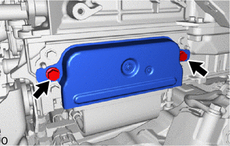
- CHECK INVERTER COVER WARNING:
Be sure to wear insulated gloves.
- Check that the service plug grip is not installed.NOTE:
After removing the service plug grip, do not turn the ignition switch to ON (READY), unless instructed by the repair information because this may cause a malfunction.
- Check if the inverter cover of the inverter with converter assembly is installed correctly.
OK
The inverter cover is installed correctly.
Result
Proceed to OK NG
Result:
NG
INSTALL PARTS CORRECTLY
Result:
OK
See step 5
- Check that the service plug grip is not installed.
- CHECK INVERTER COVER WARNING:
Be sure to wear insulated gloves.
- Check that the service plug grip is not installed.NOTE:
After removing the service plug grip, do not turn the ignition switch to ON (READY), unless instructed by the repair information because this may cause a malfunction.
- Remove the inverter cover from the inverter with converter assembly.
Refer to REMOVAL [12/2019 - 10/2022] , or refer to REMOVAL [10/2022 - 11/2023]
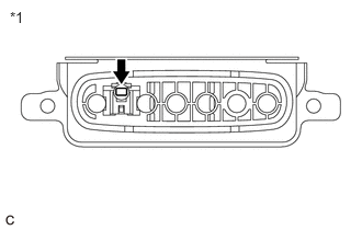
- Check the condition of the inverter cover interlock.
OK
Dirt or foreign matter has not entered the connectors and there is no evidence of contamination.
*1 Inverter Cover - Install the inverter cover.
Result
Proceed to OK NG
Result:
OK
REPLACE INVERTER WITH CONVERTER ASSEMBLY
Refer to REMOVAL [12/2019 - 10/2022] , or refer to REMOVAL [10/2022 - 11/2023]
Result:
NG
REPLACE INVERTER COVER
Refer to REMOVAL [12/2019 - 10/2022] , or refer to REMOVAL [10/2022 - 11/2023]
- Check that the service plug grip is not installed.