Drive Mode Select Switch Circuit [12/2019 - 11/2023]: Procedure
- READ VALUE USING GTS (CAN BUS CHECK)
See step 2
Result
Result Proceed to All of the ECUs and sensors that are currently connected to the CAN communication system are displayed A None of the ECUs and sensors that are currently connected to the CAN communication system are displayed, or some of them are not displayed B Result:
B
GO TO CAN COMMUNICATION SYSTEM
Refer to HOW TO PROCEED WITH TROUBLESHOOTING [12/2019 - 10/2021] , or refer to HOW TO PROCEED WITH TROUBLESHOOTING [10/2021 - 10/2022] , or refer to HOW TO PROCEED WITH TROUBLESHOOTING [10/2022 - 11/2023]
Result:
A
See step 2
- CHECK DTC OUTPUT (HEALTH CHECK)
See step 3
Result
Result Proceed to No DTCs are output A DTCs are output B Result:
B
GO TO DTC CHART
Result:
A
See step 3
- CHECK DRIVE MODE STATUS
- Turn the ignition switch to ON.
- Operate the drive mode select switch (No. 1 pattern select switch assembly) to change the drive mode.
- Check that the drive mode indicator is displayed on the multi-information display and changes according to the selected drive mode.
Result
Result Proceed to Display changes according to drive mode select switch operation A Display does not change according to drive mode select switch operation B - Turn the ignition switch off.
Result:
A
GO TO PROBLEM SYMPTOMS TABLE
Refer to PROBLEM SYMPTOMS TABLE [12/2019 - 10/2022] , or refer to PROBLEM SYMPTOMS TABLE [10/2022 - 11/2023]
Result:
B
See step 4
- READ VALUE USING GTS (DRIVE MODE SWITCH-, DRIVE MODE SWITCH+)
- Read the Data List using the GTS.
Powertrain > Hybrid Control > Data List
Tester Display Drive Mode Switch- Drive Mode Switch+ Result
Result Proceed to GTS display changes according to drive mode select switch operation A Other than above B - Turn the ignition switch off.
Result:
A
CHECK METER / GAUGE SYSTEM
Refer to HOW TO PROCEED WITH TROUBLESHOOTING [12/2019 - ]
Result:
B
See step 5
- Read the Data List using the GTS.
- INSPECT DRIVE MODE SELECT SWITCH (NO. 1 PATTERN SELECT SWITCH ASSEMBLY)
Refer to PROCEDURE - Step 3
Result
Proceed to OK NG Result:
NG
REPLACE DRIVE MODE SELECT SWITCH (NO. 1 PATTERN SELECT SWITCH ASSEMBLY)
Refer to REMOVAL [12/2019 - ]
Result:
OK
See step 6
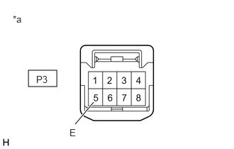
- CHECK HARNESS AND CONNECTOR (DRIVE MODE SELECT SWITCH - BODY GROUND)
- Disconnect the P3 drive mode select switch (No. 1 pattern select switch assembly) connector.
- Measure the resistance according to the value(s) in the table below.
*a Front view of wire harness connector
(to Drive Mode Select Switch (No. 1 Pattern Select Switch Assembly))Standard Resistance
Tester Connection Condition Specified Condition P3-5 (E) - Body ground Always Below 1 Ω - Reconnect the P3 drive mode select switch (No. 1 pattern select switch assembly) connector.
Result
Proceed to OK NG
Result:
NG
REPAIR OR REPLACE HARNESS OR CONNECTOR
Result:
OK
See step 7
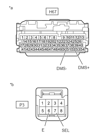
- CHECK HARNESS AND CONNECTOR (HYBRID VEHICLE CONTROL ECU - DRIVE MODE SELECT SWITCH)
- Disconnect the H67 hybrid vehicle control ECU connector.
- Disconnect the P3 drive mode select switch (No. 1 pattern select switch assembly) connector.
- Measure the resistance according to the value(s) in the table below.
*a Front view of wire harness connector
(to Hybrid Vehicle Control ECU)*b Front view of wire harness connector
(to Drive Mode Select Switch (No. 1 Pattern Select Switch Assembly))Standard Resistance
Tester Connection Condition Specified Condition H67-37 (DMS-) - P3-6 (E) Always Below 1 Ω H67-38 (DMS+) - P3-7 (SEL) Always Below 1 Ω H67-37 (DMS-) or P3-6 (E) - Body ground Always 10 kΩ or higher H67-38 (DMS+) or P3-7 (SEL) - Body ground Always 10 kΩ or higher - Reconnect the P3 drive mode select switch (No. 1 pattern select switch assembly) connector.
- Reconnect the H67 hybrid vehicle control ECU connector.
Result
Proceed to OK NG
Result:
OK
REPLACE HYBRID VEHICLE CONTROL ECU
Refer to REMOVAL [12/2019 - 10/2022] , or refer to REMOVAL [10/2022 - 11/2023]
Result:
NG
REPAIR OR REPLACE HARNESS OR CONNECTOR