TRAIL Switch Circuit [12/2019 - 11/2023]: Procedure
- READ VALUE USING GTS (CAN BUS CHECK)
See step 2
Result
Result Proceed to All of the ECUs and sensors that are currently connected to the CAN communication system are displayed A None of the ECUs and sensors that are currently connected to the CAN communication system are displayed, or some of them are not displayed B Result:
B
GO TO CAN COMMUNICATION SYSTEM. Refer to HOW TO PROCEED WITH TROUBLESHOOTING [12/2019 - 10/2021] , or refer to HOW TO PROCEED WITH TROUBLESHOOTING [10/2021 - 10/2022] , or refer to HOW TO PROCEED WITH TROUBLESHOOTING [10/2022 - 11/2023]
Result:
A
See step 2
- CHECK DTC OUTPUT (HEALTH CHECK)
See step 3
Result
Result Proceed to No DTCs are output A DTCs are output B Result:
B
GO TO DTC CHART. Refer to DIAGNOSTIC TROUBLE CODE CHART [12/2019 - 09/2020] , or Refer to DIAGNOSTIC TROUBLE CODE CHART [09/2020 - 10/2021] , or Refer to DIAGNOSTIC TROUBLE CODE CHART [10/2021 - 11/2023]
Result:
A
See step 3
- READ VALUE USING GTS (AUTO LSD SWITCH)
- Read the Data List using the GTS.
Powertrain > Hybrid Control > Data List
Tester Display Auto LSD Switch Result
Result Proceed to GTS display changes according to TRAIL mode switch operation A GTS display does not change according to TRAIL mode switch operation B - Turn the ignition switch off.
Result:
A
GO TO PROBLEM SYMPTOMS TABLES. Refer to PROBLEM SYMPTOMS TABLE [12/2019 - 10/2022] , or refer to PROBLEM SYMPTOMS TABLE [10/2022 - 11/2023]
Result:
B
See step 4
- Read the Data List using the GTS.
- INSPECT TRAIL MODE SWITCH (PATTERN SELECT SWITCH)
Refer to PROCEDURE - Step 2
Result
Proceed to OK NG Result:
NG
REPLACE TRAIL MODE SWITCH (PATTERN SELECT SWITCH). Refer to REMOVAL [12/2019 - ]
Result:
OK
See step 5
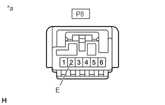
- CHECK HARNESS AND CONNECTOR (TRAIL MODE SWITCH - BODY GROUND)
- Disconnect the P8 TRAIL mode switch (pattern select switch) connector.
- Measure the resistance according to the value(s) in the table below.
*a Front view of wire harness connector
(to TRAIL Mode Switch (Pattern Select Switch))Standard Resistance
Tester Connection Condition Specified Condition P8-2 (E) - Body ground Always Below 1 Ω - Reconnect the P8 TRAIL mode switch (pattern select switch) connector.
Result
Proceed to OK NG
Result:
NG
REPAIR OR REPLACE HARNESS OR CONNECTOR
Result:
OK
See step 6
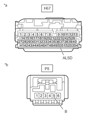
- CHECK HARNESS AND CONNECTOR (HYBRID VEHICLE CONTROL ECU - TRAIL MODE SWITCH)
- Disconnect the H67 hybrid vehicle control ECU connector.
- Disconnect the P8 TRAIL mode switch (pattern select switch) connector.
- Measure the resistance according to the value(s) in the table below.
*a Front view of wire harness connector
(to Hybrid Vehicle Control ECU)*b Front view of wire harness connector
(to TRAIL Mode Switch (Pattern Select Switch))Standard Resistance
Tester Connection Condition Specified Condition H67-36 (ALSD) - P8-5 (B) Always Below 1 Ω H67-36 (ALSD) or P8-5 (B) - Body ground Always 10 kΩ or higher - Reconnect the P8 TRAIL mode switch (pattern select switch) connector.
- Reconnect the H67 hybrid vehicle control ECU connector.
Result
Proceed to OK NG
Result:
OK
REPLACE HYBRID VEHICLE CONTROL ECU. Refer to REMOVAL [12/2019 - 10/2022] , or refer to REMOVAL [10/2022 - 11/2023]
Result:
NG
REPAIR OR REPLACE HARNESS OR CONNECTOR