Removal [12/2019 - 10/2022]: Procedure
- RECOVER REFRIGERANT FROM REFRIGERATION SYSTEM
Refer to PROCEDURE - Step 1
- REMOVE SERVICE PLUG GRIP
Refer to REMOVAL [12/2019 - 10/2022]
- CHECK TERMINAL VOLTAGE
- Remove the No. 2 inverter protector.
Refer to PROCEDURE - Step 9
- Disconnect the engine room main wire.
Refer to PROCEDURE - Step 10
- Remove the connector cover assembly.
Refer to PROCEDURE - Step 11
- Check the terminal voltage.
Refer to PROCEDURE - Step 12
- Install the connector cover assembly.
Refer to PROCEDURE - Step 7
- Connect the engine room main wire.
Refer to PROCEDURE - Step 16
- Install the No. 2 inverter protector.
Refer to PROCEDURE - Step 17
- Remove the No. 2 inverter protector.
- REMOVE DISCHARGE HOSE SUB-ASSEMBLY
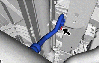
- Remove the bolt and disconnect the discharge hose sub-assembly from the cooler condenser assembly.
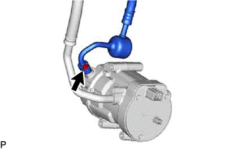
- Remove the bolt and discharge hose sub-assembly from the compressor with motor assembly.
- Remove the 2 O-rings from the discharge hose sub-assembly.NOTE:
Seal the openings of the disconnected parts using vinyl tape to prevent moisture and foreign matter from entering them.
- Remove the bolt and disconnect the discharge hose sub-assembly from the cooler condenser assembly.
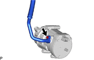
- DISCONNECT SUCTION HOSE SUB-ASSEMBLY
- REMOVE COMPRESSOR WITH MOTOR ASSEMBLY
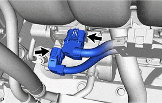
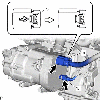
- Disconnect the 2 connectors.
- Using a screwdriver, slide the green-colored lock of the connector (A) as shown in the illustration to release it and disconnect the connector.
*a Connector (A) *b Connector (B) *c Green-colored Lock 
Slide WARNING:Make sure to wear insulated gloves.
NOTE:Insulate the disconnected terminals and connector with insulating tape.
- Disconnect the connector (B).
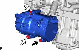
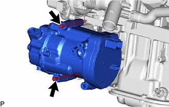
- Remove the bolt and 2 nuts.

Bolt 
Nut - Using an E8 "TORX" socket wrench, remove the 2 stud bolts and compressor with motor assembly.
- Disconnect the 2 connectors.