DTC P1BFC-A2: Battery Discharge Control Circuit System Voltage Low [12/2019 - 11/2023]: Procedure
- CHECK CONNECTOR CONNECTION CONDITION (INVERTER WITH CONVERTER ASSEMBLY CONNECTOR)
Refer to PROCEDURE - Step 3
Result
Result Proceed to OK A NG (The connector is not connected securely.) B NG (The terminals are not making secure contact or are deformed, or water or foreign matter exists in the connector.) C Result:
B
CONNECT SECURELY
Result:
C
REPAIR OR REPLACE HARNESS OR CONNECTOR
Result:
A
See step 2
- CHECK HARNESS AND CONNECTOR (DISCHARGE CONTROL POWER SOURCE CIRCUIT) WARNING:
Be sure to wear insulated gloves.
- Check that the service plug grip is not installed.NOTE:
After removing the service plug grip, do not turn the ignition switch to ON (READY), unless instructed by the repair information because this may cause a malfunction.
- Disconnect the A55 inverter with converter assembly connector.
- Measure the resistance according to the value(s) in the table below.
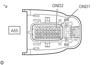
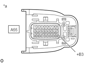
*a Front view of wire harness connector
(to Inverter with Converter Assembly)Standard Resistance
Tester Connection Condition Specified Condition A55-9 (GND1) - Body ground Ignition switch off Below 1 Ω A55-8 (GND2) - Body ground Ignition switch off Below 1 Ω - Reconnect the A55 inverter with converter assembly connector.
Result
Proceed to OK NG
Result:
NG
REPAIR OR REPLACE HARNESS OR CONNECTOR (INVERTER WITH CONVERTER ASSEMBLY - BODY GROUND)
Result:
OK
See step 3
- Check that the service plug grip is not installed.
- CHECK FUSE (MG)
- Remove the MG fuse from the No. 5 floor relay block and No. 5 floor junction block assembly.
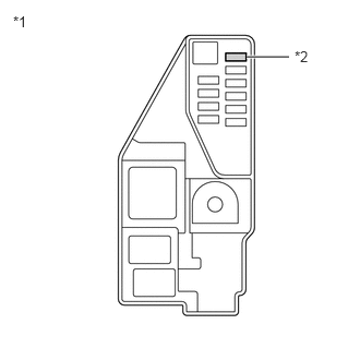
*1 No. 5 Floor Relay Block and No. 5 Floor Junction Block Assembly *2 MG Fuse - Check if there is an open circuit in the MG fuse in the No. 5 floor relay block and No. 5 floor junction block assembly.
OK
There is no open circuit in the MG fuse.
- Install the MG fuse.
Result
Proceed to OK NG
Result:
NG
REPLACE FUSE (MG)
Result:
OK
See step 4
- Remove the MG fuse from the No. 5 floor relay block and No. 5 floor junction block assembly.
- CHECK HARNESS AND CONNECTOR (MG FUSE - INVERTER WITH CONVERTER ASSEMBLY) WARNING:
Be sure to wear insulated gloves.
- Check that the service plug grip is not installed.NOTE:
After removing the service plug grip, do not turn the ignition switch to ON (READY), unless instructed by the repair information because this may cause a malfunction.
- Remove the MG fuse from the No. 5 floor relay block and No. 5 floor junction block assembly.
- Disconnect the A55 inverter with converter assembly connector.
- Measure the resistance according to the value(s) in the table below.
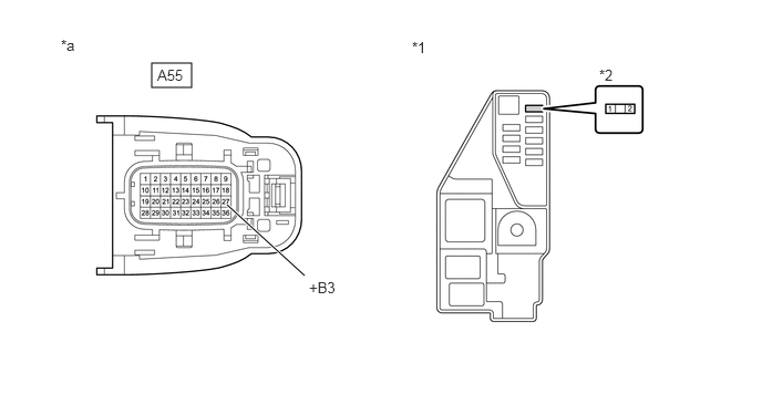
*1 No. 5 Floor Relay Block and No. 5 Floor Junction Block Assembly *2 MG Fuse Terminal *a Front view of wire harness connector
(to Inverter with Converter Assembly)- - Standard Resistance
Tester Connection Condition Specified Condition 2 (MG fuse terminal) - A55-27 (+B3) Ignition switch off Below 1 Ω - Reconnect the A55 inverter with converter assembly connector.
- Install the MG fuse.
Result
Proceed to OK NG
Result:
NG
REPAIR OR REPLACE HARNESS OR CONNECTOR
Result:
OK
See step 5
- Check that the service plug grip is not installed.
- CHECK HARNESS AND CONNECTOR (MG FUSE - AUXILIARY BATTERY TERMINAL)
- Disconnect the cable from the negative (-) auxiliary battery terminal.
- Disconnect the cable from the positive (+) auxiliary battery terminal.
- Remove the MG fuse from the No. 5 floor relay block and No. 5 floor junction block assembly.
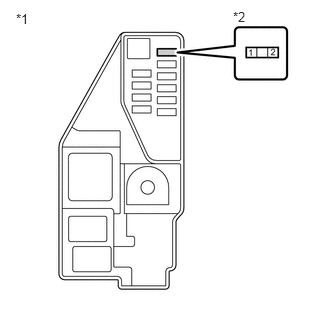
*1 No. 5 Floor Relay Block and No. 5 Floor Junction Block Assembly *2 MG Fuse Terminal - Measure the resistance according to the value(s) in the table below.
Standard Resistance
Tester Connection Condition Specified Condition 1 (MG fuse terminal) - Auxiliary battery positive (+) cable Ignition switch off Below 1 Ω 1 (MG fuse terminal) - Body ground Ignition switch off 10 kΩ or higher - Connect the cable to the positive (+) auxiliary battery terminal.
- Connect the cable to the negative (-) auxiliary battery terminal.
- Install the MG fuse.
Result
Proceed to OK NG
Result:
NG
REPAIR OR REPLACE HARNESS OR CONNECTOR
Result:
OK
See step 6
- CHECK HARNESS AND CONNECTOR (DISCHARGE CONTROL POWER SOURCE CIRCUIT) WARNING:
Be sure to wear insulated gloves.
- Check that the service plug grip is not installed.NOTE:
After removing the service plug grip, do not turn the ignition switch to ON (READY), unless instructed by the repair information because this may cause a malfunction.
- Disconnect the A55 inverter with converter assembly connector.
- Connect the cable to the negative (-) auxiliary battery terminal.
- Measure the voltage according to the value(s) in the table below.
*a Front view of wire harness connector
(to Inverter with Converter Assembly)Standard Voltage
Tester Connection Condition Specified Condition A55-27 (+B3) - Body ground Ignition switch off 11 to 14 V - Disconnect the cable from the negative (-) auxiliary battery terminal.
- Reconnect the A55 inverter with converter assembly connector.
Result
Proceed to OK NG
Result:
OK
REPLACE INVERTER WITH CONVERTER ASSEMBLY
Refer to REMOVAL [12/2019 - 10/2022] , or refer to REMOVAL [10/2022 - 11/2023]
Result:
NG
CHECK AUXILIARY BATTERY
- Check that the service plug grip is not installed.