DTC P0AA0-00: Hybrid/EV Battery Positive Contactor Circuit Stuck Closed [12/2019 - 11/2023]: Procedure
- CHECK DTC OUTPUT (HYBRID CONTROL, MOTOR GENERATOR)
- Check for DTCs.
Powertrain > Hybrid Control > Trouble Codes
Powertrain > Motor Generator > Trouble Codes
Result
Result Proceed to P0AA0-00 only is output, or DTCs except the ones in the table below are also output. A DTCs of Hybrid Control System in the tables below are output. B DTCs of Motor Generator Control System in the tables below are output. C Malfunction Content System Relevant DTC Microcomputer malfunction Hybrid Control System P0606-47 Hybrid/EV Powertrain Control Module Processor Watchdog / Safety MCU Failure P0606-87 Hybrid/EV Powertrain Control Module Processor to Monitoring Processor Missing Message P060A-47 Hybrid/EV Powertrain Control Module Monitoring Processor Watchdog / Safety MCU Failure P060A-87 Hybrid/EV Powertrain Control Module Processor from Monitoring Processor Missing Message P0A1B-49 Drive Motor "A" Control Module Internal Electronic Failure P1C9E-9F Hybrid/EV System Reset Stuck Off Motor Generator Control System P0A1B-1F Generator Control Module Circuit Intermittent P0A1A-47 Generator Control Module Watchdog / Safety MC Failure P0A1A-49 Generator Control Module Internal Electronic Failure P1C2A-1C Generator A/D Converter Circuit Circuit Voltage Out of Range P1C2A-49 Generator A/D Converter Circuit Internal Electronic Failure P1C2B-1C Drive Motor "A" Control Module A/D Converter Circuit Voltage Out of Range P1C2B-49 Drive Motor "A" Control Module A/D Converter Circuit Internal Electronic Failure P1CAC-49 Generator Position Sensor Internal Electronic Failure P1CAD-49 Drive Motor "A" Position Sensor Internal Electronic Failure P1CAF-38 Generator Position Sensor REF Signal Cycle Malfunction Signal Frequency Incorrect P1CB0-38 Drive Motor "A" Position Sensor REF Signal Frequency Incorrect P3133-83 Communication Error from Generator to Drive Motor "A" Value of Signal Protection Calculation Incorrect P3133-86 Communication Error from Generator to Drive Motor "A" Signal Invalid P3133-87 Communication Error from Generator to Drive Motor "A" Missing Message Power source circuit malfunction Motor Generator Control System P06D6-1C Generator Control Module Offset Power Circuit Voltage Out of Range P06B0-1C Generator Control Module Position Sensor REF Power Source Circuit Voltage Out of Range Communication system malfunction Hybrid Control System P3123-87 Lost Communication with Drive Motor Control Module "A" from Hybrid/EV Control Module Missing Message Sensor and actuator circuit malfunction Hybrid Control System P0AD9-11 Hybrid/EV Battery Positive Contactor Circuit Short to Ground P0AD9-15 Hybrid/EV Battery Positive Contactor Circuit Short to Auxiliary Battery or Open P0ADD-11 Hybrid/EV Battery Negative Contactor Circuit Short to Ground P0ADD-15 Hybrid/EV Battery Negative Contactor Circuit Short to Auxiliary Battery or Open P0AE4-11 Hybrid/EV Battery Precharge Contactor Circuit Short to Ground P0AE4-15 Hybrid/EV Battery Precharge Contactor Circuit Short to Auxiliary Battery or Open Motor Generator Control System P0A3F-16 Drive Motor "A" Position Sensor Circuit Voltage Below Threshold P0A4B-16 Generator Position Sensor Circuit Voltage Below Threshold P0A4B-21 Generator Position Sensor Signal Amplitude < Minimum P0A4B-22 Generator Position Sensor Signal Amplitude > Maximum P0C50-13 Drive Motor "A" Position Sensor Circuit "A" Circuit Open P0C50-16 Drive Motor "A" Position Sensor Circuit "A" Circuit Voltage Below Threshold P0C50-17 Drive Motor "A" Position Sensor Circuit "A" Circuit Voltage Above Threshold P0C5A-13 Drive Motor "A" Position Sensor Circuit "B" Circuit Open P0C5A-16 Drive Motor "A" Position Sensor Circuit "B" Circuit Voltage Below Threshold P0C5A-17 Drive Motor "A" Position Sensor Circuit "B" Circuit Voltage Above Threshold P0C64-13 Generator Position Sensor Circuit "A" Circuit Open P0C64-16 Generator Position Sensor Circuit "A" Circuit Voltage Below Threshold P0C64-17 Generator Position Sensor Circuit "A" Circuit Voltage Above Threshold P0C69-13 Generator Position Sensor Circuit "B" Circuit Open P0C69-16 Generator Position Sensor Circuit "B" Circuit Voltage Below Threshold P0C69-17 Generator Position Sensor Circuit "B" Circuit Voltage Above Threshold System malfunction Hybrid Control System P0D2D-1C Drive Motor "A" Inverter Voltage Sensor Voltage Out of Range P1C83-49 High Voltage Power Resource Circuit Voltage Sensor after Boosting Malfunction P0C76-00 Hybrid/EV Battery System Discharge Time Too Long Motor Generator Control System P0D2D-16 Drive Motor "A" Inverter Voltage Sensor (VH) Circuit Voltage Below Threshold P0D2D-17 Drive Motor "A" Inverter Voltage Sensor (VH) Circuit Voltage Above Threshold P1CB6-9E Drive Motor "A" Inverter Voltage Sensor (VH) Stuck On HINT:
- P0AA0-00 may be output as a result of the malfunction indicated by the DTCs above.
- The chart above is listed in inspection order of priority.
- Check DTCs that are output at the same time by following the listed order. (The main cause of the malfunction can be determined without performing unnecessary inspections.)
- P0AA0-00 may be output as a result of the malfunction indicated by the DTCs above.
- Turn the ignition switch off.
Result:
B
GO TO DTC CHART (HYBRID CONTROL SYSTEM)
Refer to DIAGNOSTIC TROUBLE CODE CHART [12/2019 - 09/2020] , or refer to DIAGNOSTIC TROUBLE CODE CHART [09/2020 - 10/2021] , or refer to DIAGNOSTIC TROUBLE CODE CHART [10/2021 - 11/2023]
Result:
C
GO TO DTC CHART (MOTOR GENERATOR CONTROL SYSTEM) . Refer to DIAGNOSTIC TROUBLE CODE CHART [12/2019 - 10/2021] , or refer to DIAGNOSTIC TROUBLE CODE CHART [10/2021 - 11/2023]
Result:
A
See step 2
- Check for DTCs.
- CHECK FREEZE FRAME DATA (HYBRID CONTROL)
- Read the Freeze Frame Data of DTC P0AA0-00.
Powertrain > Hybrid Control > Trouble Codes
NOTE:As freeze frame data is stored immediately before and after a DTC is stored, make sure to only read the values for the moment the DTC was stored ("0(s)").
Result
Result Proceed to Difference between "VL-Voltage before Boosting" and "VH-Voltage after Boosting" is less than 76 V. A Difference between "VL-Voltage before Boosting" and "VH-Voltage after Boosting" is 76 V or more. B HINT:
If VH-Voltage after Boosting is output even when an off command is being sent to the system main relay (positive side), P0AA0-00 is output. If the difference between the "VL-Voltage before Boosting" and the "VH-Voltage after Boosting" is large, it is determined that there is an inverter (VH sensor) malfunction.
- Turn the ignition switch off.
Result:
B
REPLACE INVERTER WITH CONVERTER ASSEMBLY
Refer to REMOVAL [12/2019 - 10/2022] , or refer to REMOVAL [10/2022 - 11/2023]
Result:
A
See step 3
- Read the Freeze Frame Data of DTC P0AA0-00.
- CHECK CONNECTOR CONNECTION CONDITION (HYBRID VEHICLE CONTROL ECU CONNECTOR)
Refer to PROCEDURE - Step 1
Result
Proceed to OK NG Result:
OK
See step 5
Result:
NG
See step 4
- CONNECT SECURELY
Result
Proceed to NEXT Result:
NEXT
See step 5
- CHECK CONNECTOR CONNECTION CONDITION (FLOOR WIRE CONNECTOR)
- Check the connection condition of the AM8 floor wire connector and the contact pressure of each terminal. Check the terminals for deformation, and check the connector for water ingress and foreign matter.
Refer to ELECTRONIC CIRCUIT INSPECTION PROCEDURE [12/2019 - ]
OK
- The connector is connected securely.
- The terminals are not deformed and are connected securely.
- No water or foreign matter in the connector.
Result
Result Proceed to OK A NG (The connector is not connected securely.) B NG (The terminals are not making secure contact or are deformed, or water or foreign matter exists in the connector.) C
Result:
A
See step 8
Result:
C
See step 7
Result:
B
See step 6
- Check the connection condition of the AM8 floor wire connector and the contact pressure of each terminal. Check the terminals for deformation, and check the connector for water ingress and foreign matter.
- CONNECT SECURELY
Result
Proceed to NEXT Result:
NEXT
See step 8
- REPAIR OR REPLACE HARNESS OR CONNECTOR
Result
Proceed to NEXT Result:
NEXT
See step 8
- CHECK CONNECTOR CONNECTION CONDITION (HV BATTERY JUNCTION BLOCK ASSEMBLY CONNECTOR) WARNING:
Be sure to wear insulated gloves.
- Check that the service plug grip is not installed.NOTE:
After removing the service plug grip, do not turn the ignition switch to ON (READY), unless instructed by the repair information because this may cause a malfunction.
- Remove the No. 10 HV battery shield panel.
Refer to REMOVAL [12/2019 - 10/2022] , or refer to REMOVAL [10/2022 - 11/2023]
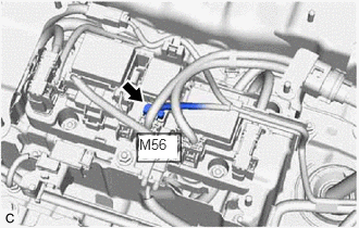
- Check the connector connections and contact pressure of the relevant terminals of the M56 HV battery junction block assembly connector.
Refer to ELECTRONIC CIRCUIT INSPECTION PROCEDURE [12/2019 - ]
OK
The connectors are connected securely and there are no contact pressure problems.
- Install the No. 10 HV battery shield panel.
Result
Proceed to OK NG
Result:
OK
See step 10
Result:
NG
See step 9
- Check that the service plug grip is not installed.
- CONNECT SECURELY
Result
Proceed to NEXT Result:
NEXT
See step 10
- CHECK GROUND WIRE CONNECTION CONDITION (SMR ACTIVATION LOW-VOLTAGE CIRCUIT)
- Check the installation condition of the ground wire MF.
OK
The ground wire MF is securely installed.
Result
Proceed to OK NG
Result:
OK
See step 12
Result:
NG
See step 11
- Check the installation condition of the ground wire MF.
- CONNECT SECURELY
Result
Proceed to NEXT Result:
NEXT
See step 12
- CHECK HARNESS AND CONNECTOR (HYBRID VEHICLE CONTROL ECU - HV BATTERY JUNCTION BLOCK ASSEMBLY) WARNING:
Be sure to wear insulated gloves.
- Check that the service plug grip is not installed.NOTE:
After removing the service plug grip, do not turn the ignition switch to ON (READY), unless instructed by the repair information because this may cause a malfunction.
- Remove the No. 10 HV battery shield panel.
Refer to REMOVAL [12/2019 - 10/2022] , or refer to REMOVAL [10/2022 - 11/2023]
- Disconnect the M56 HV battery junction block assembly connector.
- Disconnect the A32 hybrid vehicle control ECU connector.
- Measure the resistance according to the value(s) in the table below.
Standard Resistance (Check for Open)
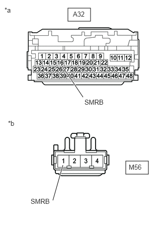
Tester Connection Condition Specified Condition A32-16 (SMRB) - M56-1 (SMRB) Ignition switch off Below 1 Ω Standard Resistance (Check for Short)
Tester Connection Condition Specified Condition A32-16 (SMRB) or M56-1 (SMRB) - Body ground and other terminals Ignition switch off 10 kΩ or higher *a Front view of wire harness connector
(to Hybrid Vehicle Control ECU)*b Front view of wire harness connector
(to HV Battery Junction Block Assembly) - Reconnect the A32 hybrid vehicle control ECU connector.
- Reconnect the M56 HV battery junction block assembly connector.
- Install the No. 10 HV battery shield panel.
Result
Proceed to OK NG
Result:
OK
See step 14
Result:
NG
See step 13
- Check that the service plug grip is not installed.
- REPAIR OR REPLACE HARNESS OR CONNECTOR
Result
Proceed to NEXT Result:
NEXT
See step 14
- CHECK HARNESS AND CONNECTOR (HV BATTERY JUNCTION BLOCK ASSEMBLY - BODY GROUND) WARNING:
Be sure to wear insulated gloves.
- Check that the service plug grip is not installed.NOTE:
After removing the service plug grip, do not turn the ignition switch to ON (READY), unless instructed by the repair information because this may cause a malfunction.
- Remove the No. 10 HV battery shield panel.
Refer to REMOVAL [12/2019 - 10/2022] , or refer to REMOVAL [10/2022 - 11/2023]
- Disconnect the M56 HV battery junction block assembly connector.
- Measure the resistance according to the value(s) in the table below.
Standard Resistance
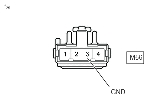
Tester Connection Condition Specified Condition M56-3 (GND) - Body ground Ignition switch off Below 1 Ω *a Front view of wire harness connector
(to HV Battery Junction Block Assembly) - Reconnect the M56 HV battery junction block assembly connector.
- Install the No. 10 HV battery shield panel.
Result
Proceed to OK NG
Result:
OK
See step 16
Result:
NG
See step 15
- Check that the service plug grip is not installed.
- REPAIR OR REPLACE HARNESS OR CONNECTOR
Result
Proceed to NEXT Result:
NEXT
See step 16
- INSPECT HV BATTERY JUNCTION BLOCK ASSEMBLY (SMRB) WARNING:
Be sure to wear insulated gloves.
- Check that the service plug grip is not installed.NOTE:
After removing the service plug grip, do not turn the ignition switch to ON (READY), unless instructed by the repair information because this may cause a malfunction.
- Remove the No. 10 HV battery shield panel.
Refer to REMOVAL [12/2019 - 10/2022] , or refer to REMOVAL [10/2022 - 11/2023]
- Disconnect the M56 HV battery junction block assembly connector.
- Measure the resistance according to the value(s) in the table below.
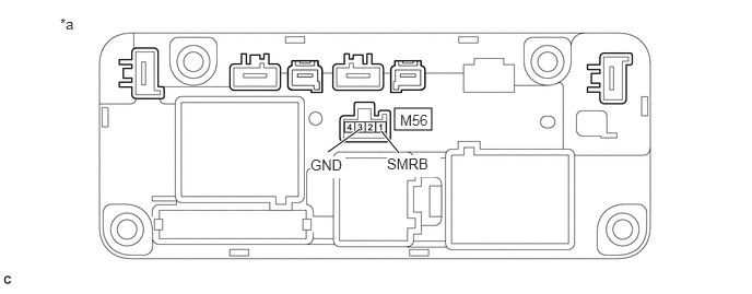
*a Component without harness connected
(HV Battery Junction Block Assembly)- - Standard Resistance
Tester Connection Condition Specified Condition M56-1 (SMRB) - M56-3 (GND) -40 to 80°C (-40 to 176°F) 25.0 to 59.0 Ω - Reconnect the M56 HV battery junction block assembly connector.
- Install the No. 10 HV battery shield panel.
Result
Proceed to OK NG
Result:
NG
See step 19
Result:
OK
See step 17
- Check that the service plug grip is not installed.
- CHECK HV BATTERY JUNCTION BLOCK ASSEMBLY (SMRB) WARNING:
Be sure to wear insulated gloves.
- Check that the service plug grip is not installed.NOTE:
After removing the service plug grip, do not turn the ignition switch to ON (READY), unless instructed by the repair information because this may cause a malfunction.
- Remove the No. 10 HV battery shield panel.
Refer to REMOVAL [12/2019 - 10/2022] , or refer to REMOVAL [10/2022 - 11/2023]
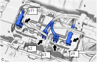
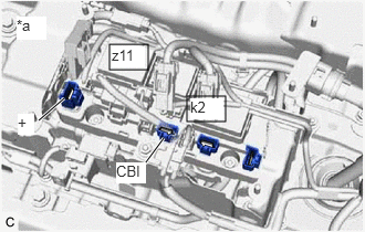
- Disconnect the 2 HV floor under wire connectors from the HV battery junction block assembly.
- Disconnect the 2 HV battery high voltage connectors from the HV battery junction block assembly.NOTE:
Insulate each disconnected high-voltage connector with insulating tape. Wrap the connector from the wire harness side to the end of the connector.
- Measure the resistance according to the value(s) in the table below.
Standard Resistance
Tester Connection Condition Specified Condition k2-1 (CBI) - z11-1 (+) Ignition switch off 10 kΩ or higher HINT:
- If a system main relay is stuck closed, inspect the HV battery junction block assembly without removing it from the vehicle, in order to keep the relay closed.
- If the result of reading the freeze frame data is A, the HV battery junction block assembly must be replaced. Measuring resistance can determine that this is either a present or past malfunction.
*a Component without harness connected
(HV Battery Junction Block Assembly) - Reconnect the 2 HV battery high voltage connectors.
- Reconnect the 2 HV floor under wire connectors.
- Install the No. 10 HV battery shield panel.
Result
Result Judgment Proceed to OK Past malfunction A NG Present malfunction B
Result:
B
See step 20
Result:
A
See step 18
- Check that the service plug grip is not installed.
- REPLACE HV BATTERY JUNCTION BLOCK ASSEMBLY
Refer to REMOVAL [12/2019 - 10/2022] , or refer to REMOVAL [10/2022 - 11/2023]
Result
Proceed to NEXT Result:
NEXT
See step 21
- REPLACE HV BATTERY JUNCTION BLOCK ASSEMBLY
Refer to REMOVAL [12/2019 - 10/2022] , or refer to REMOVAL [10/2022 - 11/2023]
Result
Proceed to NEXT Result:
NEXT
See step 21
- REPLACE HV BATTERY JUNCTION BLOCK ASSEMBLY
Refer to REMOVAL [12/2019 - 10/2022] , or refer to REMOVAL [10/2022 - 11/2023]
Result
Proceed to NEXT Result:
NEXT
See step 21
- CHECK HYBRID VEHICLE CONTROL ECU (CHECK FOR NORMAL OPERATION) WARNING:
Be sure to wear insulated gloves.
- Install the service plug grip.
- Clear the DTCs.
Powertrain > Hybrid Control > Clear DTCs
- Turn the ignition switch off and wait for 2 minutes or more.
- Turn the ignition switch to ON (READY).
- According to the display on the GTS, read the Data List and monitor the values of "Hybrid Battery Voltage" and "VL-Voltage before Boosting" for 3 minutes.
Powertrain > Hybrid Control > Data List
Tester Display VL-Voltage before Boosting Hybrid Battery Voltage Result
Result Proceed to Difference between "Hybrid Battery Voltage" and "VL-Voltage before Boosting" is always less than 100 V. A Difference between "Hybrid Battery Voltage" and "VL-Voltage before Boosting" is 100 V or more. B - Turn the ignition switch off.
Result:
A
END
Result:
B
REPLACE HYBRID VEHICLE CONTROL ECU AND HV BATTERY JUNCTION BLOCK ASSEMBLY
HYBRID VEHICLE CONTROL ECU: Refer to REMOVAL [12/2019 - 10/2022] , or refer to REMOVAL [10/2022 - 11/2023]
HV BATTERY JUNCTION BLOCK ASSEMBLY: Refer to REMOVAL [12/2019 - 10/2022] , or refer to REMOVAL [10/2022 - 11/2023]