DTC P2600-31: Motor/Generator Coolant Pump "A" Control Circuit No Signal [12/2019 - 11/2023]: Procedure
- READ VALUE USING GTS (MOTOR/GENERATOR COOLING OIL PUMP MOTOR REVOLUTION)
- Set the Duty ratio to 90%.
HINT:
The active test is not performed when the Duty ratio is 50% or lower or 95% or higher, or the ambient temperature is 0°C (30°F) or lower.
Powertrain > Hybrid Control > Active Test
Active Test Display Control the Motor/Generator Cooling Oil Pump Data List Display Motor/Generator Cooling Oil Pump Motor Revolution - According to the display on the GTS, perform the Active Test "Control the Motor/Generator Cooling Oil Pump" and, check the value of the Data List item "Motor/Generator Cooling Oil Pump Motor Revolution".
OK
Tester Display Condition Specified Condition Motor/Generator Cooling Oil Pump Motor Revolution Ignition switch ON
During Active Test160 to 7600 rpm - Turn the ignition switch off.
Result
Proceed to OK NG
Result:
NG
See step 3
Result:
OK
See step 2
- Set the Duty ratio to 90%.
- CHECK FOR INTERMITTENT PROBLEMS
Refer to CHECK FOR INTERMITTENT PROBLEMS [12/2019 - 11/2023]
Result
Proceed to OK NG Result:
OK
REPLACE HYBRID VEHICLE CONTROL ECU. Refer to REMOVAL [12/2019 - 10/2022] , or refer to REMOVAL [10/2022 - 11/2023]
Result:
NG
REPAIR OR REPLACE MALFUNCTIONING PARTS, COMPONENT AND AREA
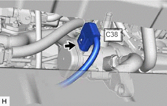
- CHECK CONNECTOR CONNECTION CONDITION (OIL PUMP WITH MOTOR ASSEMBLY CONNECTOR)
- Check the connector connections and contact pressure of the relevant terminals for the C38 oil pump with motor assembly connector.
Refer to ELECTRONIC CIRCUIT INSPECTION PROCEDURE [12/2019 - ]
OK
The connector is connected securely and there are no contact problems.
Result
Proceed to OK NG
Result:
NG
CONNECT SECURELY
Result:
OK
See step 4
- Check the connector connections and contact pressure of the relevant terminals for the C38 oil pump with motor assembly connector.
- CHECK CONNECTOR CONNECTION CONDITION (HYBRID VEHICLE CONTROL ECU CONNECTOR)
Refer to PROCEDURE - Step 1
Result
Proceed to OK NG Result:
NG
CONNECT SECURELY
Result:
OK
See step 5
- CHECK HARNESS AND CONNECTOR (OIL PUMP WITH MOTOR ASSEMBLY POWER SOURCE CIRCUIT)
- Disconnect the C38 oil pump with motor assembly connector.
- Set the Duty ratio to 90%.
HINT:
The active test is not performed when the Duty ratio is 50% or lower or 95% or higher, or the ambient temperature is 0°C (30°F) or lower.
Powertrain > Hybrid Control > Active Test
Tester Display Control the Motor/Generator Cooling Oil Pump - Measure the voltage according to the value(s) in the table below.
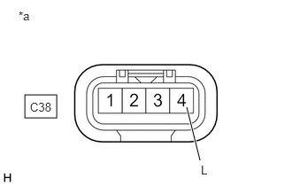
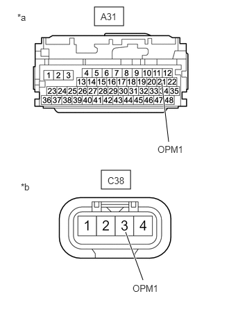
*a Front view of wire harness connector
(to Oil Pump with Motor Assembly)Standard Voltage
Tester Connection Condition Specified Condition C38-4 (L) - Body ground Ignition switch ON
During Active Test11 to 14 V NOTE:Turning the ignition switch to ON with the oil pump with motor assembly connector disconnected causes other DTCs to be stored. Clear the DTCs after performing this inspection.
- Turn the ignition switch off.
- Reconnect the C38 oil pump with motor assembly connector.
Result
Proceed to OK NG
Result:
NG
See step 9
Result:
OK
See step 6
- CHECK HARNESS AND CONNECTOR (OIL PUMP WITH MOTOR ASSEMBLY - BODY GROUND)
- Disconnect the C38 oil pump with motor assembly connector.
- Measure the resistance according to the value(s) in the table below.
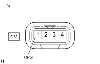
*a Front view of wire harness connector
(to Oil Pump with Motor Assembly)Standard Resistance
Tester Connection Condition Specified Condition C38-1 (OPG) - Body ground Ignition switch off Below 1 Ω - Reconnect the C38 oil pump with motor assembly connector.
Result
Proceed to OK NG
Result:
NG
REPAIR OR REPLACE HARNESS OR CONNECTOR
Result:
OK
See step 7
- CHECK HARNESS AND CONNECTOR (HYBRID VEHICLE CONTROL ECU - OIL PUMP WITH MOTOR ASSEMBLY)
- Disconnect the A31 hybrid vehicle control ECU connector.
- Disconnect the C38 oil pump with motor assembly connector.
- Measure the resistance according to the value(s) in the table below.
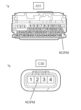
*a Front view of wire harness connector
(to Hybrid Vehicle Control ECU)*b Front view of wire harness connector
(to Oil Pump with Motor Assembly)Standard Resistance (Check for Open)
Tester Connection Condition Specified Condition A31-22 (NOPM) - C38-2 (NOPM) Ignition switch off Below 1 Ω Standard Resistance (Check for Short)
Tester Connection Condition Specified Condition A31-22 (NOPM) or C38-2 (NOPM) - Body ground and other terminals Ignition switch off 10 kΩ or higher - Reconnect the C38 oil pump with motor assembly connector.
- Reconnect the A31 hybrid vehicle control ECU connector.
Result
Proceed to OK NG
Result:
NG
REPAIR OR REPLACE HARNESS OR CONNECTOR
Result:
OK
See step 8
- CHECK HARNESS AND CONNECTOR (HYBRID VEHICLE CONTROL ECU - OIL PUMP WITH MOTOR ASSEMBLY)
- Disconnect the A31 hybrid vehicle control ECU connector.
- Disconnect the C38 oil pump with motor assembly connector.
- Measure the resistance according to the value(s) in the table below.
*a Front view of wire harness connector
(to Hybrid Vehicle Control ECU)*b Front view of wire harness connector
(to Oil Pump with Motor Assembly)Standard Resistance (Check for Open)
Tester Connection Condition Specified Condition A31-21 (OPM1) - C38-3 (OPM1) Ignition switch off Below 1 Ω Standard Resistance (Check for Short)
Tester Connection Condition Specified Condition A31-21 (OPM1) or C38-3 (OPM1) - Body ground and other terminals Ignition switch off 10 kΩ or higher - Turn the ignition switch to ON.
- Measure the voltage according to the value(s) in the table below.
Standard Voltage
Tester Connection Condition Specified Condition A31-21 (OPM1) or C38-3 (OPM1) - Body ground Ignition switch ON Below 1 V NOTE:Turning the ignition switch to ON with the hybrid vehicle control ECU and oil pump with motor assembly connectors disconnected causes other DTCs to be stored. Clear the DTCs after performing this inspection.
- Turn the ignition switch off.
- Reconnect the C38 oil pump with motor assembly connector.
- Reconnect the A31 hybrid vehicle control ECU connector.
Result
Proceed to OK NG
Result:
OK
REPLACE OIL PUMP WITH MOTOR ASSEMBLY. Refer to REMOVAL [12/2019 - 11/2023]
Result:
NG
REPAIR OR REPLACE HARNESS OR CONNECTOR
- CHECK FUSE (OIL PMP)
- Remove the OIL PMP fuse from the No. 1 engine room relay block and No. 1 junction block assembly.
- Measure the resistance according to the value(s) in the table below.
Standard Resistance
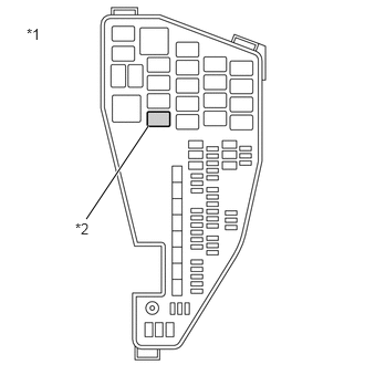
Tester Connection Condition Specified Condition OIL PMP fuse Always Below 1 Ω *1 No. 1 Engine Room Relay Block and No. 1 Junction Block Assembly *2 OIL PMP Fuse - Install the OIL PMP fuse.
Result
Proceed to OK NG
Result:
NG
REPLACE FUSE (OIL PMP)
Result:
OK
See step 10
- INSPECT RELAY (OIL PMP)
- Remove the OIL PMP relay from the No. 1 engine room relay block and No. 1 junction block assembly.
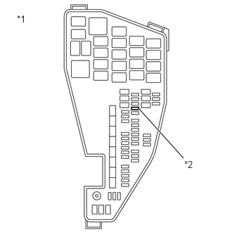
*1 No. 1 Engine Room Relay Block and No. 1 Junction Block Assembly *2 OIL PMP Relay - Measure the resistance according to the value(s) in the table below.
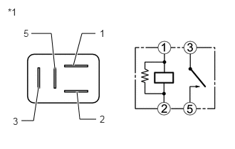
*1 OIL PMP Relay Standard Resistance
Tester Connection Condition Specified Condition 3 - 5 Auxiliary battery voltage not applied between terminals 1 and 2 10 kΩ or higher Auxiliary battery voltage applied between terminals 1 and 2 Below 1 Ω - Install the OIL PMP relay.
Result
Proceed to OK NG
Result:
OK
REPAIR OR REPLACE HARNESS OR CONNECTOR (OIL PUMP WITH MOTOR ASSEMBLY POWER SOURCE CIRCUIT)
Result:
NG
REPLACE RELAY (OIL PMP)
- Remove the OIL PMP relay from the No. 1 engine room relay block and No. 1 junction block assembly.