DTC P2120-12: Throttle/Pedal Position Sensor/Switch "D" Circuit Short to Auxiliary Battery; DTC P2120-14: Throttle/Pedal Position Sensor/Switch "D" Circuit Short to Ground or Open; DTC P2120-1C: Throttle/Pedal Position Sensor/Switch "D" Voltage Out of Range; DTC P2120-1F: Throttle/Pedal Position Sensor/Switch "D" Circuit Intermittent; DTC P2125-12: Throttle/Pedal Position Sensor/Switch "E" Circuit Short to Auxiliary Battery; DTC P2125-14: Throttle/Pedal Position Sensor/Switch "E" Circuit Short to Ground or Open; DTC P2125-1C: Throttle/Pedal Position Sensor/Switch "E" Voltage Out of Range; DTC P2125-1F: Throttle/Pedal Position Sensor/Switch "E" Circuit Intermittent; DTC P2138-00: Throttle/Pedal Position Sensor/Switch "D"/" E" Voltage Correlation; DTC P2138-2B: Throttle/Pedal Position Sensor/Switch "D"/"E" Signal Cross Coupled [12/2019 - 11/2023]: Procedure
- READ VALUE USING GTS (ACCELERATOR POSITION SENSOR NO. 1 VOLTAGE %, ACCELERATOR POSITION SENSOR NO. 2 VOLTAGE %)
- Read the Data List.
Powertrain > Hybrid Control > Data List
Tester Display Accelerator Position Sensor No. 1 Voltage % Accelerator Position Sensor No. 2 Voltage % Standard
Tester Display Accelerator Pedal Condition Specified Condition Accelerator Position Sensor No. 1 Voltage % Not depressed 10 to 22% Fully depressed 52 to 90% Not depressed → Fully depressed → Not depressed (Accelerator pedal should be operated slowly) Value changes progressively Accelerator Position Sensor No. 2 Voltage % Not depressed 24 to 40% Fully depressed 68 to 99% Not depressed → Fully depressed → Not depressed (Accelerator pedal should be operated slowly) Value changes progressively - Turn the ignition switch off.
Result
Proceed to OK NG
Result:
OK
CHECK FOR INTERMITTENT PROBLEMS. Refer to CHECK FOR INTERMITTENT PROBLEMS [12/2019 - 11/2023]
Result:
NG
See step 2
- Read the Data List.
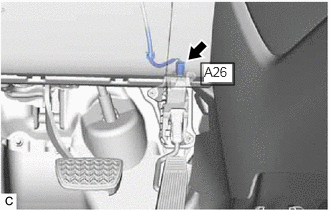
- CHECK CONNECTOR CONNECTION CONDITION (ACCELERATOR PEDAL SENSOR ASSEMBLY CONNECTOR)
- Check the connector connections and contact pressure of the relevant terminals for the accelerator pedal sensor assembly connector.
Refer to ELECTRONIC CIRCUIT INSPECTION PROCEDURE [12/2019 - ]
OK
The connectors are connected securely and there are no contact pressure problems.
Result
Proceed to OK NG
Result:
NG
CONNECT SECURELY
Result:
OK
See step 3
- Check the connector connections and contact pressure of the relevant terminals for the accelerator pedal sensor assembly connector.
- CHECK CONNECTOR CONNECTION CONDITION (HYBRID VEHICLE CONTROL ECU CONNECTOR)
Refer to PROCEDURE - Step 1
Result
Proceed to OK NG Result:
NG
CONNECT SECURELY
Result:
OK
See step 4
- CHECK HYBRID VEHICLE CONTROL ECU (CHECK VOLTAGE)
- Disconnect the A26 accelerator pedal sensor assembly connector.
- Turn the ignition switch to ON.
- Measure the voltage according to the value(s) in the table below.
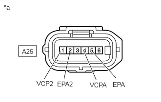
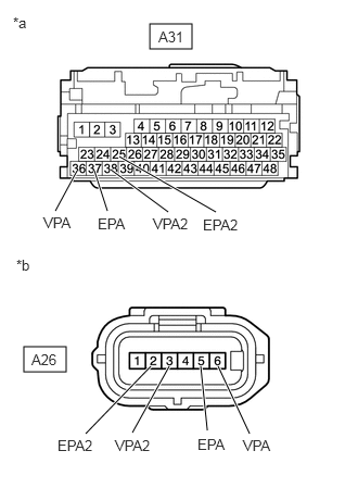
*a Front view of wire harness connector
(to Accelerator Pedal Sensor Assembly)Standard Voltage
Tester Connection Condition Specified Condition A26-4 (VCPA) - A26-5 (EPA) Ignition switch ON 4.5 to 5.5 V A26-1 (VCP2) - A26-2 (EPA2) Ignition switch ON 4.5 to 5.5 V - Turn the ignition switch off.
- Reconnect the A26 accelerator pedal sensor assembly connector.
Result
Proceed to OK NG
Result:
NG
See step 6
Result:
OK
See step 5
- CHECK HYBRID VEHICLE CONTROL ECU (CHECK RESISTANCE)
- Disconnect the A26 accelerator pedal sensor assembly connector.
- Measure the resistance according to the value(s) in the table below.
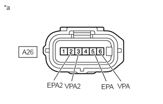
*a Front view of wire harness connector
(to Accelerator Pedal Sensor Assembly)Standard Resistance
Tester Connection Condition Specified Condition A26-6 (VPA) - A26-5 (EPA) Ignition switch off 28.00 to 41.61 kΩ A26-3 (VPA2) - A26-2 (EPA2) Ignition switch off 28.00 to 41.61 kΩ - Reconnect the A26 accelerator pedal sensor assembly connector.
Result
Proceed to OK NG
Result:
OK
REPLACE ACCELERATOR PEDAL SENSOR ASSEMBLY. Refer to REMOVAL [12/2019 - ]
Result:
NG
See step 7
- CHECK HARNESS AND CONNECTOR (HYBRID VEHICLE CONTROL ECU - ACCELERATOR PEDAL SENSOR ASSEMBLY)
- Disconnect the A31 hybrid vehicle control ECU connector.
- Disconnect the A26 accelerator pedal sensor assembly connector.
- Turn the ignition switch to ON.
- Measure the voltage according to the value(s) in the table below.
Standard Voltage
Tester Connection Condition Specified Condition A31-24 (VCPA) - Body ground Ignition switch ON Below 1 V A31-37 (EPA) - Body ground Ignition switch ON Below 1 V A31-26 (VCP2) - Body ground Ignition switch ON Below 1 V A31-25 (EPA2) - Body ground Ignition switch ON Below 1 V NOTE:Turning the ignition switch to ON with the hybrid vehicle control ECU connector disconnected causes other DTCs to be stored. Clear the DTCs after performing this inspection.
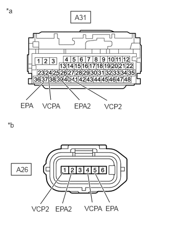
*a Front view of wire harness connector
(to Hybrid Vehicle Control ECU)*b Front view of wire harness connector
(to Accelerator Pedal Sensor Assembly) - Turn the ignition switch off.
- Measure the resistance according to the value(s) in the table below.
Standard Resistance (Check for Open)
Tester Connection Condition Specified Condition A31-24 (VCPA) - A26-4 (VCPA) Ignition switch off Below 1 Ω A31-37 (EPA) - A26-5 (EPA) Ignition switch off Below 1 Ω A31-26 (VCP2) - A26-1 (VCP2) Ignition switch off Below 1 Ω A31-25 (EPA2) - A26-2 (EPA2) Ignition switch off Below 1 Ω Standard Resistance (Check for Short)
Tester Connection Condition Specified Condition A31-24 (VCPA) or A26-4 (VCPA) - Body ground and other terminals Ignition switch off 10 kΩ or higher A31-37 (EPA) or A26-5 (EPA) - Body ground and other terminals Ignition switch off 10 kΩ or higher A31-26 (VCP2) or A26-1 (VCP2) - Body ground and other terminals Ignition switch off 10 kΩ or higher A31-25 (EPA2) or A26-2 (EPA2) - Body ground and other terminals Ignition switch off 10 kΩ or higher - Reconnect the A26 accelerator pedal sensor assembly connector.
- Reconnect the A31 hybrid vehicle control ECU connector.
Result
Proceed to OK NG
Result:
OK
REPLACE HYBRID VEHICLE CONTROL ECU. Refer to REMOVAL [12/2019 - 10/2022] , or refer to REMOVAL [10/2022 - 11/2023]
Result:
NG
REPAIR OR REPLACE HARNESS OR CONNECTOR
- CHECK HARNESS AND CONNECTOR (HYBRID VEHICLE CONTROL ECU - ACCELERATOR PEDAL SENSOR ASSEMBLY)
- Disconnect the A31 hybrid vehicle control ECU connector.
- Disconnect the A26 accelerator pedal sensor assembly connector.
- Turn the ignition switch to ON.
- Measure the voltage according to the value(s) in the table below.
Standard Voltage
Tester Connection Condition Specified Condition A31-36 (VPA) - Body ground Ignition switch ON Below 1 V A31-38 (VPA2) - Body ground Ignition switch ON Below 1 V A31-37 (EPA) - Body ground Ignition switch ON Below 1 V A31-25 (EPA2) - Body ground Ignition switch ON Below 1 V NOTE:Turning the ignition switch to ON with the hybrid vehicle control ECU connector disconnected causes other DTCs to be stored. Clear the DTCs after performing this inspection.
*a Front view of wire harness connector
(to Hybrid Vehicle Control ECU)*b Front view of wire harness connector
(to Accelerator Pedal Sensor Assembly) - Turn the ignition switch off.
- Measure the resistance according to the value(s) in the table below.
Standard Resistance (Check for Open)
Tester Connection Condition Specified Condition A31-36 (VPA) - A26-6 (VPA) Ignition switch off Below 1 Ω A31-37 (EPA) - A26-5 (EPA) Ignition switch off Below 1 Ω A31-38 (VPA2) - A26-3 (VPA2) Ignition switch off Below 1 Ω A31-25 (EPA2) - A26-2 (EPA2) Ignition switch off Below 1 Ω Standard Resistance (Check for Short)
Tester Connection Condition Specified Condition A31-36 (VPA) or A26-6 (VPA) - Body ground and other terminals Ignition switch off 10 kΩ or higher A31-37 (EPA) or A26-5 (EPA) - Body ground and other terminals Ignition switch off 10 kΩ or higher A31-38 (VPA2) or A26-3 (VPA2) - Body ground and other terminals Ignition switch off 10 kΩ or higher A31-25 (EPA2) or A26-2 (EPA2) - Body ground and other terminals Ignition switch off 10 kΩ or higher - Reconnect the A26 accelerator pedal sensor assembly connector.
- Reconnect the A31 hybrid vehicle control ECU connector.
Result
Proceed to OK NG
Result:
OK
REPLACE HYBRID VEHICLE CONTROL ECU. Refer to REMOVAL [12/2019 - 10/2022] , or refer to REMOVAL [10/2022 - 11/2023]
Result:
NG
REPAIR OR REPLACE HARNESS OR CONNECTOR