DTC P2600-71: Motor/Generator Coolant Pump "A" Actuator Stuck; DTC P2B86-00: Coolant Pump "A" Overspeed/Air in System [12/2019 - 11/2023]: Procedure
- CHECK DTC OUTPUT (HYBRID CONTROL)
- Check for DTCs.
Powertrain > Hybrid Control > Trouble Codes
Result
Result Proceed to DTC P2600-71 or P2B86-00 only is output, or DTCs except the ones in the tables below are also output. A DTC P2600-71 or P2B86-00 and any of the DTCs in the following table are output at the same time. B Relevant DTC P274A-11 Transmission Fluid Temperature Sensor "C" Circuit Short to Ground P274A-15 Transmission Fluid Temperature Sensor "C" Circuit Short to Auxiliary Battery or Open P274A-1C Transmission Fluid Temperature Sensor "C" Voltage Out of Range P274A-1F Transmission Fluid Temperature Sensor "C" Circuit Intermittent HINT:
The transmission fluid temperature sensor value is used to detect DTC P2600-71 and P2B86-00. Check that the transmission fluid temperature sensor operates normally, as the detection condition for DTC P2600-71 or P2B86-00 may be mistakenly detected due to a malfunction in the transmission fluid temperature sensor.
- Turn the ignition switch off.
Result:
B
GO TO DTC CHART (HYBRID CONTROL SYSTEM). Refer to DIAGNOSTIC TROUBLE CODE CHART [12/2019 - 09/2020] , or refer to DIAGNOSTIC TROUBLE CODE CHART [09/2020 - 10/2021] , or refer to DIAGNOSTIC TROUBLE CODE CHART [10/2021 - 11/2023]
Result:
A
See step 2
- Check for DTCs.
- CHECK OIL PIPE
- Check that there is no clogging in the oil pipes connected to the oil pump with motor assembly, oil cooler assembly and hybrid vehicle transaxle assembly.
Result
Proceed to OK NG
Result:
NG
REPAIR OR REPLACE OIL PIPE
Result:
OK
See step 3
- Check that there is no clogging in the oil pipes connected to the oil pump with motor assembly, oil cooler assembly and hybrid vehicle transaxle assembly.
- CHECK CONNECTOR CONNECTION CONDITION (OIL PUMP WITH MOTOR ASSEMBLY CONNECTOR)
See step 3
Result
Proceed to OK NG Result:
NG
CONNECT SECURELY
Result:
OK
See step 4
- CHECK CONNECTOR CONNECTION CONDITION (HYBRID VEHICLE CONTROL ECU CONNECTOR)
Refer to PROCEDURE - Step 1
Result
Proceed to OK NG Result:
NG
CONNECT SECURELY
Result:
OK
See step 5
- CHECK HARNESS AND CONNECTOR (OIL PUMP WITH MOTOR ASSEMBLY POWER SOURCE CIRCUIT)
See step 5
Result
Proceed to OK NG Result:
NG
See step 11
Result:
OK
See step 6
- CHECK HARNESS AND CONNECTOR (OIL PUMP WITH MOTOR ASSEMBLY - BODY GROUND)
See step 6
Result
Proceed to OK NG Result:
NG
REPAIR OR REPLACE HARNESS OR CONNECTOR
Result:
OK
See step 7
- CHECK HARNESS AND CONNECTOR (HYBRID VEHICLE CONTROL ECU - OIL PUMP WITH MOTOR ASSEMBLY)
See step 7
Result
Proceed to OK NG Result:
NG
REPAIR OR REPLACE HARNESS OR CONNECTOR
Result:
OK
See step 8
- CHECK HARNESS AND CONNECTOR (HYBRID VEHICLE CONTROL ECU - OIL PUMP WITH MOTOR ASSEMBLY)
See step 8
Result
Proceed to OK NG Result:
NG
REPAIR OR REPLACE HARNESS OR CONNECTOR
Result:
OK
See step 9
- PERFORM ACTIVE TEST USING GTS (CONTROL THE MOTOR/GENERATOR COOLING OIL PUMP MOTOR)
- Set the Duty ratio to 90%.
HINT:
The active test is not performed when the Duty ratio is 50% or lower or 95% or higher, or the ambient temperature is 0°C (30°F) or lower.
Powertrain > Hybrid Control > Active Test
Tester Display Control the Motor/Generator Cooling Oil Pump - Confirm that the oil pump with motor assembly is operating.
OK
The oil pump with motor assembly is operating.
- Turn the ignition switch off.
Result
Proceed to OK NG
Result:
NG
See step 13
Result:
OK
See step 10
- Set the Duty ratio to 90%.
- INSPECT OIL PUMP WITH MOTOR ASSEMBLY
- Remove the oil pump with motor assembly.
Refer to REMOVAL [12/2019 - 11/2023]
- Measure the resistance according to the value(s) in the table below.
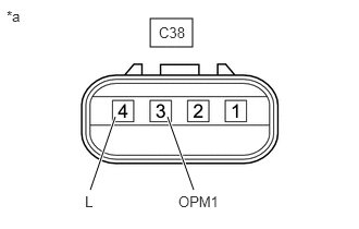
*a Component without harness connected
(Oil Pump with Motor Assembly)Standard Resistance
Tester Connection
(Tester Probe Polarity)Condition Specified Condition C38-3 (OPM1) (+) - C38-4 (L) (-) Ignition switch off 10 kΩ or higher NOTE:Make sure to check the polarity of each terminal (positive (+) or negative (-)) before connecting a tester.
- Install the oil pump with motor assembly.
Result
Proceed to OK NG
Result:
OK
REPLACE HYBRID VEHICLE CONTROL ECU. Refer to REMOVAL [12/2019 - 10/2022] , or refer to REMOVAL [10/2022 - 11/2023]
Result:
NG
REPLACE OIL PUMP WITH MOTOR ASSEMBLY. Refer to REMOVAL [12/2019 - 11/2023]
- Remove the oil pump with motor assembly.
- CHECK FUSE (OIL PMP)
See step 9
Result
Proceed to OK NG Result:
NG
REPLACE FUSE (OIL PMP)
Result:
OK
See step 12
- INSPECT RELAY (OIL PMP)
See step 10
Result
Proceed to OK NG Result:
OK
REPAIR OR REPLACE HARNESS OR CONNECTOR (OIL PUMP WITH MOTOR ASSEMBLY POWER SOURCE CIRCUIT)
Result:
NG
REPLACE RELAY (OIL PMP)
- INSPECT OIL PUMP WITH MOTOR ASSEMBLY
- Remove the oil pump with motor assembly.
Refer to REMOVAL [12/2019 - 11/2023]
- Set the Toyota Electrical Tester to diode check mode.
- Measure the voltage according to the value(s) in the table below.
*a Component without harness connected
(Oil Pump with Motor Assembly)Standard Voltage
Tester Connection
(Tester Probe Polarity)Condition Specified Condition C38-3 (OPM1) (-) - C38-4 (L) (+) Ignition switch off 1.5 V or higher NOTE:Make sure to check the polarity of each terminal (positive (+) or negative (-)) before connecting a tester.
- Install the oil pump with motor assembly.
Result
Proceed to OK NG
Result:
NG
REPLACE OIL PUMP WITH MOTOR ASSEMBLY. Refer to REMOVAL [12/2019 - 11/2023]
Result:
OK
See step 14
- Remove the oil pump with motor assembly.
- INSPECT HYBRID VEHICLE CONTROL ECU
- Set the Duty ratio to 90%.
HINT:
The active test is not performed when the Duty ratio is 50% or lower or 95% or higher, or the ambient temperature is 0°C (30°F) or lower.
Powertrain > Hybrid Control > Active Test
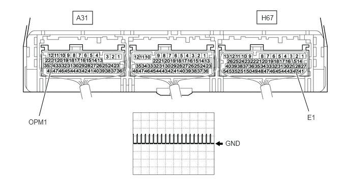
Tester Display Control the Motor/Generator Cooling Oil Pump - Connect an oscilloscope to the C38 oil pump with motor assembly connector and check the waveform.
*a Component with harness connected
(Hybrid Vehicle Control ECU)- - Item Content Tester Connection A31-21 (OPM1) - H67-3 (E1) Equipment Setting 10 V/DIV., 20 ms./DIV. Condition Ignition switch ON
During Active TestResult
Result Proceed to 11 to 14 V A Except above B - Turn the ignition switch off.
Result:
A
REPLACE HYBRID VEHICLE CONTROL ECU. Refer to REMOVAL [12/2019 - 10/2022] , or refer to REMOVAL [10/2022 - 11/2023]
Result:
B
REPLACE OIL PUMP WITH MOTOR ASSEMBLY. Refer to REMOVAL [12/2019 - 11/2023]
- Set the Duty ratio to 90%.