Disassembly [10/2022 - 11/2023]: Procedure
- PRECAUTION WARNING:
Be sure to read Precaution thoroughly before servicing.
Refer to PRECAUTION [12/2019 - 11/2023]
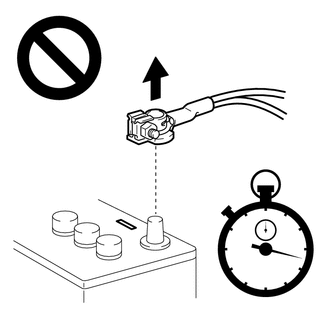
NOTE:After turning the ignition switch off, waiting time may be required before disconnecting the cable from the negative (-) auxiliary battery terminal. Therefore, make sure to read the disconnecting the cable from the negative (-) auxiliary battery terminal notices before proceeding with work.
- REMOVE BATTERY SERVICE HOLE COVER (for HV Model)
Refer to PROCEDURE - Step 1
- DISCONNECT CABLE FROM NEGATIVE AUXILIARY BATTERY TERMINAL
for T24A-FTS:
Refer to PROCEDURE - Step 1
for A25A-FXS:
Refer to PROCEDURE - Step 2
- REMOVE FRONT DOOR LOWER FRAME BRACKET GARNISH
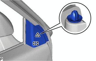
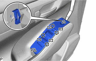
- REMOVE MULTIPLEX NETWORK MASTER SWITCH ASSEMBLY WITH FRONT DOOR UPPER ARMREST BASE PANEL (for Driver Side)
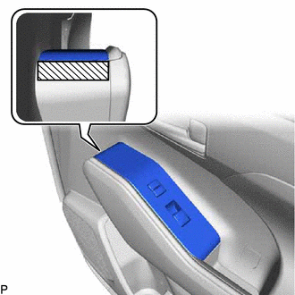
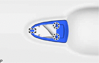
- Apply protective tape to the front door trim board sub-assembly as shown in the illustration.

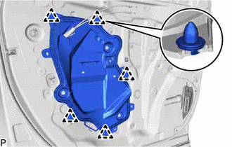
Protective Tape - Using a moulding remover, disengage the 2 clips, 4 claws and 5 guides as shown in the illustration.
- Disconnect each connector to remove the multiplex network master switch assembly with front door upper armrest base panel.
- Apply protective tape to the front door trim board sub-assembly as shown in the illustration.
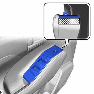
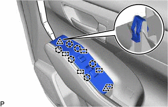
- REMOVE POWER WINDOW REGULATOR SWITCH ASSEMBLY WITH FRONT DOOR UPPER ARMREST BASE PANEL (for Front Passenger Side)
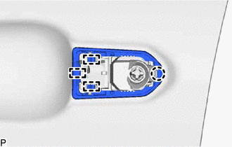
- Apply protective tape to the front door trim board sub-assembly as shown in the illustration.
Protective Tape - Using a moulding remover, disengage the 2 clips, 6 claws and 5 guides as shown in the illustration.
- Disconnect each connector to remove the power window regulator switch assembly with front door upper armrest base panel.
- Apply protective tape to the front door trim board sub-assembly as shown in the illustration.
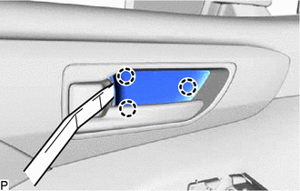
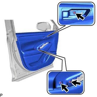
- REMOVE FRONT DOOR INSIDE HANDLE BEZEL
- REMOVE COURTESY LIGHT ASSEMBLY
Refer to PROCEDURE - Step 1
- REMOVE FRONT DOOR TRIM BOARD SUB-ASSEMBLY
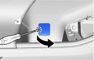
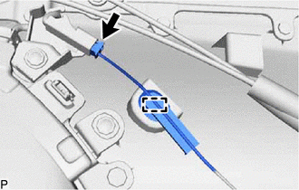
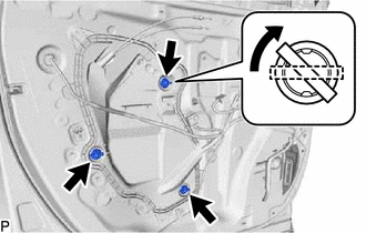
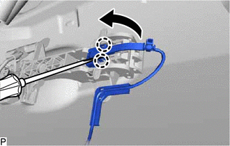
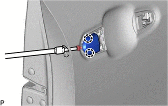
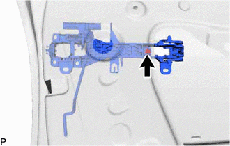
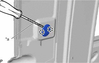
- Using a screwdriver with its tip wrapped with protective tape, disengage the claw as shown in the illustration.
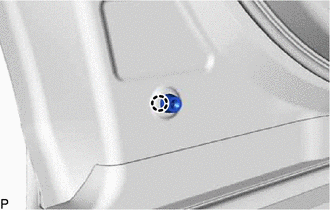
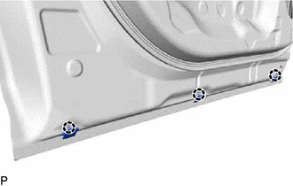
*a Protective Tape - Remove the 3 screws.
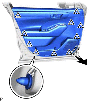
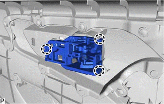
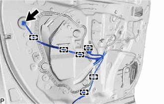
- Disengage the 10 clips as shown in the illustration.

Place Hand Here 
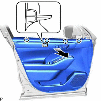
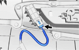
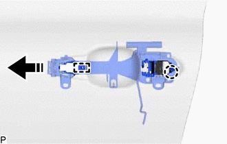
Remove in this Direction - Disengage the 4 claws and guide as shown in the illustration.
Remove in this Direction - w/ Illumination:
- w/ Seat Memory Switch:
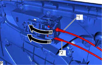
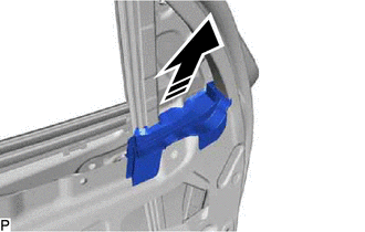
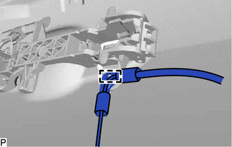
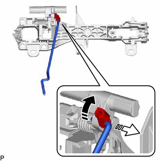
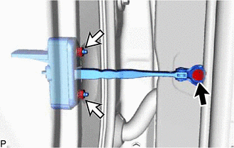
- Disconnect the front door lock open lever remote control cable and front door inside lock/unlock knob locking cable as shown in the illustration to remove the front door trim board sub-assembly.
*1 Front Door Inside Lock/Unlock Knob Locking Cable *2 Front Door Lock Open Lever Remote Control Cable Remove in this Direction
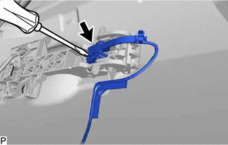
- Using a screwdriver with its tip wrapped with protective tape, disengage the claw as shown in the illustration.
- REMOVE FRONT DOOR INSIDE HANDLE SUB-ASSEMBLY
- REMOVE DOOR ARMREST COVER SUB-ASSEMBLY
- REMOVE SEAT MEMORY SWITCH (w/ Seat Memory Switch)
Refer to PROCEDURE - Step 6
- REMOVE DOOR FRAME GARNISH
- REMOVE OUTER MIRROR CONTROL ECU ASSEMBLY (w/ Memory)
Refer to PROCEDURE - Step 7
- REMOVE OUTER MIRROR INSTALL HOLE COVER
Refer to PROCEDURE - Step 7
- REMOVE OUTER REAR VIEW MIRROR ASSEMBLY WITH COVER
Refer to PROCEDURE - Step 8
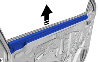
- REMOVE FRONT DOOR INNER GLASS WEATHERSTRIP
- REMOVE FRONT DOOR VENT SEAL
- REMOVE FRONT DOOR PANEL PROTECTOR
- REMOVE FRONT NO. 1 SPEAKER ASSEMBLY
Refer to PROCEDURE - Step 7
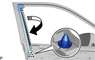
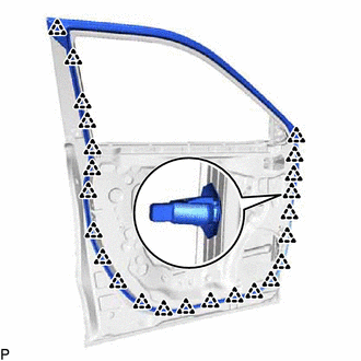
- REMOVE FRONT DOOR WEATHERSTRIP CLIP
- REMOVE FRONT DOOR SERVICE HOLE COVER
- REMOVE SIDE AIRBAG SENSOR ASSEMBLY
Refer to PROCEDURE - Step 12
- REMOVE FRONT DOOR GLASS SUB-ASSEMBLY
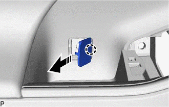
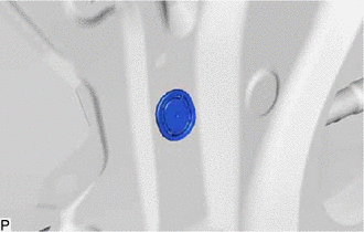
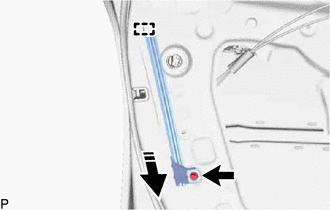
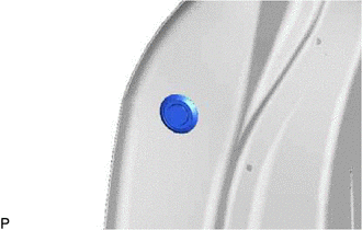
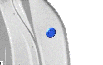
- Remove the hole plug.
- for Driver Side:
- Connect the power window regulator master switch assembly.
- for Front Passenger Side:
- Connect the power window regulator switch assembly.
- Connect the cable to the negative (-) auxiliary battery terminal.
- Turn the ignition switch to ON.
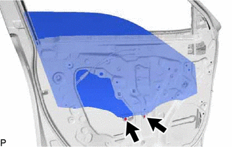
- Move the front door glass sub-assembly so that the door glass bolts can be seen.
- Turn the ignition switch off.
- Disconnect the cable from the negative (-) auxiliary battery terminal.
- for Driver Side:
- Disconnect the power window regulator master switch assembly.
- for Front Passenger Side:
- Disconnect the power window regulator switch assembly.
- Remove the 2 bolts.NOTE:
After the bolts are removed, do not allow the front door glass sub-assembly to fall.
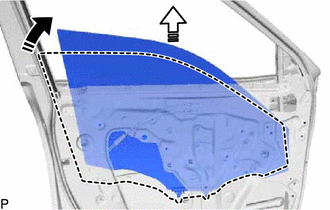
- Remove the front door glass sub-assembly as shown in the illustration.
Remove in this Direction (1) 
Remove in this Direction (2) NOTE:Do not damage the front door glass sub-assembly.
- Remove the hole plug.
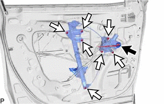
- REMOVE FRONT DOOR WINDOW REGULATOR ASSEMBLY
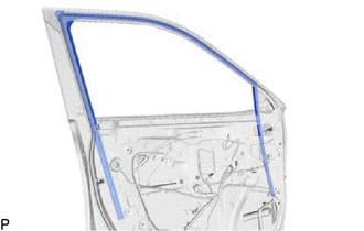
- REMOVE FRONT DOOR GLASS RUN
- REMOVE FRONT DOOR REAR LOWER FRAME SUB-ASSEMBLY
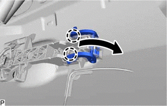
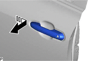
- REMOVE FRONT DOOR OUTSIDE HANDLE ASSEMBLY
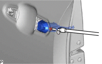
- REMOVE FRONT DOOR LOCK CYLINDER ASSEMBLY (for Driver Side)
- REMOVE FRONT DOOR OUTSIDE HANDLE COVER (for Front Passenger Side)
- REMOVE FRONT DOOR FRONT OUTSIDE HANDLE PAD
- REMOVE FRONT DOOR REAR OUTSIDE HANDLE PAD
- REMOVE FRONT DOOR LOCK WITH MOTOR ASSEMBLY
Refer to PROCEDURE - Step 12
- REMOVE FRONT DOOR OUTSIDE HANDLE FRAME SUB-ASSEMBLY
- REMOVE FRONT DOOR LOCK OPEN ROD
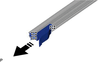
- REMOVE FRONT DOOR BELT MOULDING ASSEMBLY
Refer to PROCEDURE - Step 14
- REMOVE FRONT DOOR WINDOW FRAME MOULDING
Refer to PROCEDURE - Step 3
- REMOVE FRONT DOOR UPPER WINDOW FRAME MOULDING
Refer to PROCEDURE - Step 4
- REMOVE FRONT DOOR FRONT LOWER FRAME UPPER COVER
Refer to PROCEDURE - Step 2
- REMOVE DOOR WINDOW FRAME MOULDING CLIP
- REMOVE FRONT DOOR PANEL CUSHION
- REMOVE FRONT DOOR OUTSIDE MOULDING SUB-ASSEMBLY
Refer to PROCEDURE - Step 1
- REMOVE FRONT DOOR UPPER OUTSIDE MOULDING PAD
Refer to PROCEDURE - Step 2
- REMOVE FRONT DOOR DUST PROOF SEAL
- REMOVE FRONT DOOR CHECK ASSEMBLY
- REMOVE FRONT DOOR WEATHERSTRIP