Installation [12/2019 - 10/2022]: Procedure
- INSTALL OIL COOLER BRACKET
HINT:
Perform this procedure only when replacement of the oil cooler bracket is necessary.
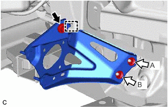
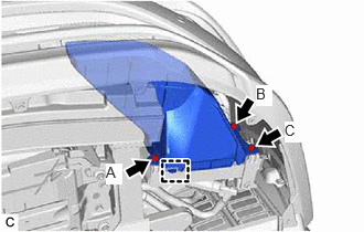
- Engage the guide and install the oil cooler bracket to the vehicle body with the bolt and 2 nuts.

Bolt 
Nut Torque: 6.0 N.m (61 kgf/cm, 53 in.lbf)
NOTE:When tightening the nuts (A and B), make sure not to lift the oil cooler bracket.
HINT:
Tightening order: Temporarily tighten bolt → Fully tighten nut (A) → Fully tighten nut (B) → Fully tighten bolt
- Engage the guide and install the oil cooler bracket to the vehicle body with the bolt and 2 nuts.
- INSTALL TRANSMISSION OIL THERMOSTAT
HINT:
Perform this procedure only when replacement of the transmission oil thermostat is necessary.
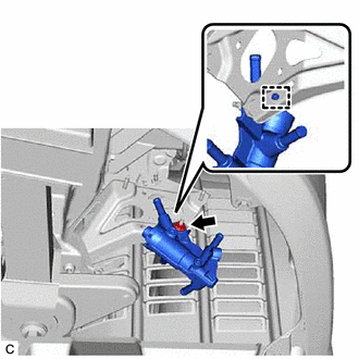
- Engage the guide and install the transmission oil thermostat to the oil cooler bracket with the nut.
Torque: 6.0 N.m (61 kgf/cm, 53 in.lbf)
- Install the oil cooler bracket to the transmission oil thermostat with the bolt.
Torque: 6.0 N.m (61 kgf/cm, 53 in.lbf)
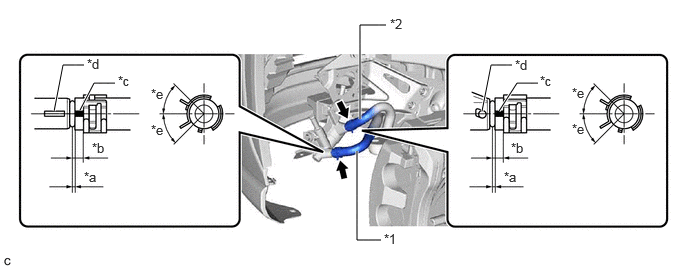
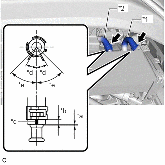
- Connect the No. 3 transmission oil cooler hose and outlet No. 1 oil cooler hose to the transmission oil thermostat and slide the 2 clips to secure them.
*1 No. 3 Transmission Oil Cooler Hose *2 Outlet No. 1 Oil Cooler Hose *a 0 to 3 mm (0 to 0.118 in.) *b 2 to 7 mm (0.0787 to 0.276 in.) *c Paint Mark *d Rib *e 45° (Claw of Clip Location) - - NOTE:- Make sure to slide the No. 3 transmission oil cooler hose and outlet No. 1 oil cooler hose until they contact the hose stopper of the transmission oil thermostat.
- Make sure to align the paint mark of the No. 3 transmission oil cooler hose and outlet No. 1 oil cooler hose with the rib of the transmission oil thermostat.
- Make sure that the claws of the clip are within the location shown in the illustration.
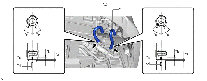
- Install the No. 1 transmission oil cooler hose and No. 2 transmission oil cooler hose to the transmission oil thermostat and slide the 2 clips to secure them.
*1 No. 1 Transmission Oil Cooler Hose *2 No. 2 Transmission Oil Cooler Hose *a 0 to 3 mm (0 to 0.118 in.) *b 2 to 7 mm (0.0787 to 0.276 in.) *c Paint Mark *d Rib *e 45° (Claw of Clip Location) - - NOTE:- Make sure to slide the No. 1 transmission oil cooler hose and No. 2 transmission oil cooler hose until they contact the hose stopper of the transmission oil thermostat.
- Make sure to align the paint mark of the No. 1 transmission oil cooler hose and No. 2 transmission oil cooler hose with the rib of the transmission oil thermostat.
- Make sure that the claws of the clip are within the location shown in the illustration.
- Engage the guide and install the transmission oil thermostat to the oil cooler bracket with the nut.
- INSTALL OIL COOLER ASSEMBLY
- Install the oil cooler assembly to the oil cooler bracket with the 2 nuts and bolt.
Torque: 6.0 N.m (61 kgf/cm, 53 in.lbf)
- Install the oil cooler assembly to the oil cooler bracket with the 2 nuts and bolt.
- CONNECT OIL COOLER HOSE
- Connect the No. 1 transmission oil cooler hose and No. 2 transmission oil cooler hose to the oil cooler assembly and slide the 2 clips to secure them.
*1 No. 1 Transmission Oil Cooler Hose *2 No. 2 Transmission Oil Cooler Hose *a 0 to 3 mm (0 to 0.118 in.) *b 2 to 7 mm (0.0787 to 0.276 in.) *c Paint Mark (Front Side of Oil Cooler Assembly) *d 30° (Paint Mark Location) *e 45° (Claw of Clip Location) NOTE:- Make sure to slide the No. 1 transmission oil cooler hose and No. 2 transmission oil cooler hose until each contacts the hose stopper of the oil cooler assembly.
- Make sure that each paint mark and the claws of each clip are within the location shown in the illustration.
- Connect the No. 1 transmission oil cooler hose and No. 2 transmission oil cooler hose to the oil cooler assembly and slide the 2 clips to secure them.
- INSTALL TRANSMISSION OIL COOLER AIR DUCT
- ADJUST AUTOMATIC TRANSAXLE FLUID
Refer to ADJUSTMENT [12/2019 - 10/2022]
- INSPECT FOR AUTOMATIC TRANSAXLE FLUID LEAK
- INSTALL FRONT FENDER APRON SEAL LH
Refer to PROCEDURE - Step 74 [12/2019 - 09/2020] , or refer to PROCEDURE - Step 74 [09/2020 - 10/2022]
- INSTALL REAR ENGINE UNDER COVER LH
Refer to PROCEDURE - Step 79 [12/2019 - 09/2020] , or refer to PROCEDURE - Step 79 [09/2020 - 10/2022]
- INSTALL NO. 1 ENGINE UNDER COVER
Refer to PROCEDURE - Step 80 [12/2019 - 09/2020] , or refer to PROCEDURE - Step 80 [09/2020 - 10/2022]
- INSTALL FRONT WHEEL OPENING EXTENSION PAD LH
Refer to PROCEDURE - Step 81 [12/2019 - 09/2020] , or refer to PROCEDURE - Step 81 [09/2020 - 10/2022]
- INSTALL FRONT WHEEL OPENING EXTENSION PAD RH
Refer to PROCEDURE - Step 82 [12/2019 - 09/2020] , or refer to PROCEDURE - Step 82 [09/2020 - 10/2022]