Installation [12/2019 - ]: Procedure
WARNING: This page is about a different variant/trim than selected.
- INSTALL HV WATER PUMP BRACKET SUB-ASSEMBLY
HINT:
Perform this procedure only when replacement of the HV water pump bracket sub-assembly is necessary.
- Install the HV water pump bracket sub-assembly to the front side member sub-assembly with the 2 bolts.
Torque: 5.0 N.m (51 kgf/cm, 44 in.lbf)
- Install the HV water pump bracket sub-assembly to the front side member sub-assembly with the 2 bolts.
- INSTALL INVERTER WATER PUMP ASSEMBLY
- Temporarily install the inverter water pump assembly to the HV water pump bracket sub-assembly with the 2 bolts.NOTE:
If the inverter water pump assembly has been struck or dropped, replace it.
- Fully tighten the 2 bolts.
Torque: 7.0 N.m (71 kgf/cm, 62 in.lbf)
- Connect the inverter water pump assembly connector.NOTE:
If a dustproof cap is installed to the inverter water pump assembly connector, do not remove it until the connector is to be connected.
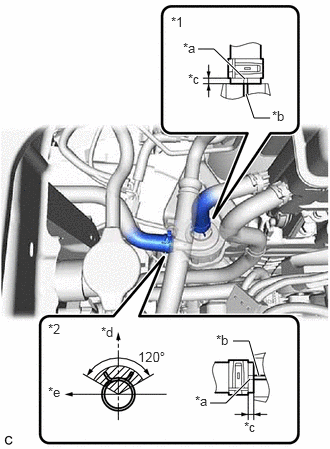
- Connect the No. 2 inverter cooling hose and No. 3 inverter cooling hose to the inverter water pump assembly and slide the 2 clips to secure them.
*1 No. 2 Inverter Cooling Hose *2 No. 3 Inverter Cooling Hose *a Alignment Mark *b Rib *c 2 to 7 mm (0.0787 to 0.276 in.) *d Up *e LH Side NOTE:- Make sure to align the alignment marks of the hoses with the ribs of the inverter water pump assembly.
- To prevent foreign matter from entering the inverter water pump assembly and inverter cooling system, do not remove the pieces of cloth from the pipes and disconnected hoses until installation.
- Do not apply excessive force to the hoses.
HINT:
Make sure that the clips are positioned as shown in the illustration.
- Temporarily install the inverter water pump assembly to the HV water pump bracket sub-assembly with the 2 bolts.
- ADD COOLANT (for Inverter)
Refer to PROCEDURE - Step 2
- INSPECT FOR COOLANT LEAK (for Inverter)
Refer to PROCEDURE - Step 1