DTC P0791-12: Intermediate Shaft Speed Sensor "A" Circuit Short to Battery; DTC P0791-14: Intermediate Shaft Speed Sensor "A" Circuit Short to Ground or Open; DTC P0791-31: Intermediate Shaft Speed Sensor "A" No Signal [12/2019 - 10/2022]: Procedure
- READ VALUE USING GTS (NC SENSOR SPEED AND NC SENSOR VOLTAGE)
- Read the Data List according to the display on the GTS.
Powertrain > Transmission > Data List
Tester Display Measurement Item Range Normal Condition Diagnostic Note NC Sensor Speed Counter gear speed Min.: 0 rpm
Max.: 12750 rpm- - NC Sensor Voltage NC sensor voltage Min.: 0.000 V
Max.: 4.999 V0.1 to 1.9 V: Engine idling - Powertrain > Transmission > Data List
Tester Display NC Sensor Speed NC Sensor Voltage Result
Result Proceed to Data List values are normal A Data List values are not normal B
Result:
A
See step 5
Result:
B
See step 2
- Read the Data List according to the display on the GTS.
- INSPECT TRANSMISSION REVOLUTION SENSOR (NC) (NC TERMINAL)
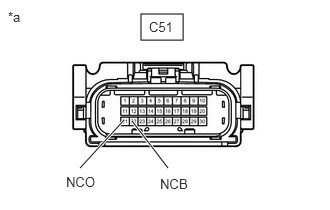
- Disconnect the C51 transmission wire connector.
*a Front view of wire harness connector
(to Transmission Wire) - Measure the resistance according to the value(s) in the table below.
Standard Resistance
Tester Connection Condition Specified Condition C51-21 (NCO) - Body ground Always 99 to 101 Ω - Turn the ignition switch to ON.
- Measure the voltage according to the value(s) in the table below.
Standard Voltage
Tester Connection Condition Specified Condition C51-22 (NCB) - Body ground Ignition switch ON 11 to 14 V Result
Proceed to OK NG
Result:
NG
See step 4
Result:
OK
See step 3
- Disconnect the C51 transmission wire connector.
- INSPECT TRANSMISSION WIRE (TRANSMISSION REVOLUTION SENSOR (NC))
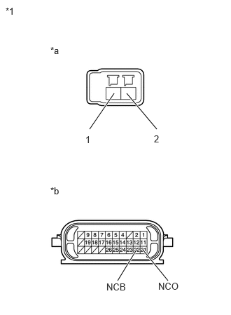
- Disconnect the transmission revolution sensor (NC) connector.
*1 Transmission Wire *a Transmission Revolution Sensor (NC) Side *b Wire Harness Connector Side Refer to REMOVAL [12/2019 - 10/2022]
- Disconnect the C51 transmission wire connector.
- Measure the resistance according to the value(s) in the table below.
Standard Resistance
Tester Connection Condition Specified Condition 1 (transmission revolution sensor (NC) side) - 22 (NCB) (wire harness connector side) Always Below 1 Ω 2 (transmission revolution sensor (NC) side) - 21 (NCO) (wire harness connector side) Always Below 1 Ω 1 (transmission revolution sensor (NC) side) or 22 (NCB) (wire harness connector side) - Body ground Always 10 kΩ or higher 2 (transmission revolution sensor (NC) side) or 21 (NCO) (wire harness connector side) - Body ground Always 10 kΩ or higher Result
Proceed to OK NG
Result:
OK
REPLACE TRANSMISSION REVOLUTION SENSOR (NC). Refer to COMPONENTS [12/2019 - 10/2022]
Result:
NG
REPAIR OR REPLACE TRANSMISSION WIRE. Refer to COMPONENTS [12/2019 - 10/2022]
- Disconnect the transmission revolution sensor (NC) connector.
- CHECK HARNESS AND CONNECTOR (TRANSMISSION WIRE - ECM)
- Disconnect the C51 transmission wire connector.
- Disconnect the C54 ECM connector.
- Measure the resistance according to the value(s) in the table below.
Standard Resistance
Tester Connection Condition Specified Condition C51-22 (NCB) - C54-73 (NCB) Always Below 1 Ω C51-21 (NCO) - C54-72 (NCO) Always Below 1 Ω C51-22 (NCB) or C54-73 (NCB) - Body ground Always 10 kΩ or higher C51-21 (NCO) or C54-72 (NCO) - Body ground Always 10 kΩ or higher Result
Proceed to OK NG
Result:
NG
REPAIR OR REPLACE HARNESS OR CONNECTOR (TRANSMISSION WIRE - ECM)
Result:
OK
See step 5
- REPLACE ECM
- Replace the ECM.
Refer to COMPONENTS [12/2019 - 10/2022]
Result
Proceed to NEXT
Result:
NEXT
PERFORM REGISTRATION. Refer to REGISTRATION [12/2019 - 10/2022]
- Replace the ECM.