Transmission Control Switch Circuit [12/2019 - 10/2022]: Procedure
- READ VALUE USING GTS (Shift SW Status (S Range))
- Read the Data List according to the display on the GTS.
Powertrain > Engine > Data List
Tester Display Measurement Item Range Normal Condition Diagnostic Note Shift SW Status (S Range) Sport (M) mode select switch status ON or OFF - ON: Shift lever in M, "+" or "-"
- OFF: Shift lever not in M, "+" or "-"
- Powertrain > Engine > Data List
Tester Display Shift SW Status (S Range) Result
Result Proceed to Data List value is normal A Data List value is not normal B
Result:
B
See step 6
Result:
A
See step 2
- Read the Data List according to the display on the GTS.
- READ VALUE USING GTS (SPORT SHIFT UP SW AND SPORT SHIFT DOWN SW)
- Read the Data List according to the display on the GTS.
Powertrain > Engine > Data List
Tester Display Measurement Item Range Normal Condition Diagnostic Note Sport Shift Up SW Sport shift up switch status ON or OFF - ON: Shift lever held in "+"
- OFF: Shift lever not held in "+"
- Sport Shift Down SW Sport shift down switch status ON or OFF - ON: Shift lever held in "-"
- OFF: Shift lever not held in "-"
- Powertrain > Engine > Data List
Tester Display Sport Shift Up SW Sport Shift Down SW Result
Result Proceed to Data List values are normal A Data List values are not normal B
Result:
A
PROCEED TO NEXT SUSPECTED AREA SHOWN IN PROBLEM SYMPTOMS TABLE. Refer to PROBLEM SYMPTOMS TABLE [12/2019 - 10/2022]
Result:
B
See step 3
- Read the Data List according to the display on the GTS.
- INSPECT TRANSMISSION CONTROL SWITCH (SHIFT LOCK CONTROL UNIT ASSEMBLY)
- Disconnect the H29 transmission control switch connector.
- Measure the resistance according to the value(s) in the table below.
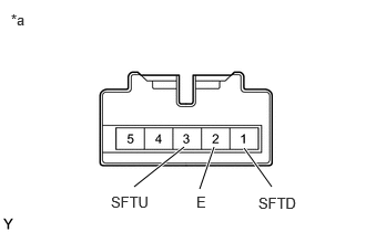
*a Component without harness connected
(Transmission Control Switch (Shift Lock Control Unit Assembly))Standard Resistance
Tester Connection Condition Specified Condition 3 (SFTU) - 2 (E) Shift lever held in "+" (Up shift) Below 1 Ω Shift lever not held in "+" (Up shift) 10 kΩ or higher 1 (SFTD) - 2 (E) Shift lever held in "-" (Down shift) Below 1 Ω Shift lever not held in "-" (Down shift) 10 kΩ or higher Result
Proceed to OK NG
Result:
NG
REPLACE TRANSMISSION CONTROL SWITCH (SHIFT LOCK CONTROL UNIT ASSEMBLY). Refer to COMPONENTS [12/2019 - 10/2022]
Result:
OK
See step 4
- CHECK HARNESS AND CONNECTOR (TRANSMISSION CONTROL SWITCH - BODY GROUND)
- Disconnect the H29 transmission control switch connector.
- Measure the resistance according to the value(s) in the table below.
Standard Resistance
Tester Connection Condition Specified Condition H29-2 (E) - Body ground Always Below 1 Ω Result
Proceed to OK NG
Result:
NG
REPAIR OR REPLACE HARNESS OR CONNECTOR (TRANSMISSION CONTROL SWITCH - BODY GROUND)
Result:
OK
See step 5
- CHECK HARNESS AND CONNECTOR (TRANSMISSION CONTROL SWITCH - ECM)
- Connect the H29 transmission control switch connector.
- Disconnect the A28 ECM connector.
- Measure the resistance according to the value(s) in the table below.
Standard Resistance
Tester Connection Condition Specified Condition A28-38 (SFTU) - Body ground Shift lever held in "+" (Up shift) Below 1 Ω A28-38 (SFTU) - Body ground Shift lever not held in "+" (Up shift) 10 kΩ or higher A28-37 (SFTD) - Body ground Shift lever held in "-" (Down shift) Below 1 Ω A28-37 (SFTD) - Body ground Shift lever not held in "-" (Down shift) 10 kΩ or higher Result
Proceed to OK NG
Result:
OK
PROCEED TO NEXT SUSPECTED AREA SHOWN IN PROBLEM SYMPTOMS TABLE. Refer to PROBLEM SYMPTOMS TABLE [12/2019 - 10/2022]
Result:
NG
REPAIR OR REPLACE HARNESS OR CONNECTOR (TRANSMISSION CONTROL SWITCH - ECM)
- INSPECT TRANSMISSION CONTROL SWITCH (SHIFT LOCK CONTROL UNIT ASSEMBLY)
- Disconnect the H29 transmission control switch connector.
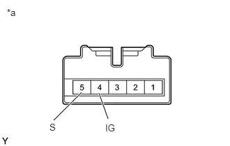
*a Component without harness connected
(Transmission Control Switch (Shift Lock Control Unit Assembly)) - Measure the resistance according to the value(s) in the table below.
Standard Resistance
Tester Connection Condition Specified Condition 4 (IG) - 5 (S) Shift lever in M, "+" or "-" Below 1 Ω Shift lever not in M, "+" or "-" 10 kΩ or higher Result
Proceed to OK NG
Result:
NG
REPLACE TRANSMISSION CONTROL SWITCH (SHIFT LOCK CONTROL UNIT ASSEMBLY). Refer to COMPONENTS [12/2019 - 10/2022]
Result:
OK
See step 7
- Disconnect the H29 transmission control switch connector.
- CHECK HARNESS AND CONNECTOR (TRANSMISSION CONTROL SWITCH (POWER SOURCE))
- Disconnect the H29 transmission control switch connector.
- Turn the ignition switch to ON.
- Measure the voltage according to the value(s) in the table below.
Standard Voltage
Tester Connection Condition Specified Condition H29-4 (IG) - Body ground Ignition switch ON 11 to 14 V Result
Proceed to OK NG
Result:
NG
REPAIR OR REPLACE HARNESS OR CONNECTOR (TRANSMISSION CONTROL SWITCH (POWER SOURCE))
Result:
OK
See step 8
- CHECK HARNESS AND CONNECTOR (TRANSMISSION CONTROL SWITCH - ECM)
- Disconnect the H29 transmission control switch connector.
- Disconnect the A28 ECM connector.
- Measure the resistance according to the value(s) in the table below.
Standard Resistance
Tester Connection Condition Specified Condition H29-5 (S) - A28-17 (S) Always Below 1 Ω H29-5 (S) or A28-17 (S) - Body ground and other terminals Always 10 kΩ or higher Result
Proceed to OK NG
Result:
OK
PROCEED TO NEXT SUSPECTED AREA SHOWN IN PROBLEM SYMPTOMS TABLE. Refer to PROBLEM SYMPTOMS TABLE [12/2019 - 10/2022]
Result:
NG
REPAIR OR REPLACE HARNESS OR CONNECTOR (TRANSMISSION CONTROL SWITCH - ECM)