Installation [10/2022 - 11/2023]: Procedure
- TEMPORARILY INSTALL AIR CONDITIONER UNIT ASSEMBLY
Refer to PROCEDURE - Step 1
- INSTALL CENTER HEATER TO REGISTER DUCT
Refer to PROCEDURE - Step 2
- INSTALL INSTRUMENT PANEL REINFORCEMENT ASSEMBLY WITH AIR CONDITIONER UNIT ASSEMBLY
Refer to PROCEDURE - Step 3
- INSTALL NO. 2 INSTRUMENT PANEL BRACE SUB-ASSEMBLY
Refer to PROCEDURE - Step 4
- INSTALL NO. 1 INSTRUMENT PANEL BRACE SUB-ASSEMBLY
Refer to PROCEDURE - Step 5
- INSTALL AIR CONDITIONER UNIT ASSEMBLY
Refer to PROCEDURE - Step 6
- CONNECT INSTRUMENT PANEL WIRE
- Connect the earth wire with the bolt.
Torque: 10 N.m (102 kgf/cm, 7 ft.lbf)
- Engage each clamp.
- Connect the 2 connectors.
- Engage each clamp.
- Install the 2 nuts.
Torque: 5.0 N.m (51 kgf/cm, 44 in.lbf)
- Connect the connector holder with the bolt (B).
Torque: 12.5 N.m (127 kgf/cm, 9 ft.lbf)
- w/ PTC Heater:
- Connect the earth wire with the bolt (A).
Torque: 8.5 N.m (87 kgf/cm, 75 in.lbf)
- Connect the connector.
- Connect the earth wire with the bolt (A).
- Connect the 4 earth wires with the 4 bolts (A).
Torque: 8.5 N.m (87 kgf/cm, 75 in.lbf)
- Connect the connector.
- Connect the earth wire with the bolt.
- INSTALL CENTER HEATER TO REGISTER SUB DUCT
Refer to PROCEDURE - Step 8
- INSTALL NO. 3 DASH PANEL INSULATOR PAD
Refer to PROCEDURE - Step 9
- INSTALL REAR NO. 3 AIR DUCT
Refer to PROCEDURE - Step 10
- INSTALL REAR NO. 4 AIR DUCT
Refer to PROCEDURE - Step 11
- INSTALL REAR NO. 1 AIR DUCT
Refer to PROCEDURE - Step 12
- INSTALL REAR NO. 2 AIR DUCT
Refer to PROCEDURE - Step 13
- INSTALL ACCELERATOR PEDAL
Refer to PROCEDURE - Step 1
- INSTALL ACCELERATOR PEDAL PAD
Refer to PROCEDURE - Step 2
- INSTALL COOLER (ROOM TEMP. SENSOR) THERMISTOR (for Automatic Air Conditioning System)
Refer to PROCEDURE - Step 16
- INSTALL NO. 1 CLEARANCE WARNING BUZZER
Refer to PROCEDURE - Step 1
- INSTALL PARKING ASSIST ECU WITH BRACKET
Refer to PROCEDURE - Step 3
- INSTALL ECU INTEGRATION BOX RH
Refer to PROCEDURE - Step 2
- INSTALL STEERING COLUMN ASSEMBLY
Refer to INSTALLATION [10/2022 - 11/2023]
- INSTALL NO. 4 AIR DUCT SUB-ASSEMBLY
See step 4
- INSTALL METER MIRROR SUB-ASSEMBLY (w/ Headup Display)
Refer to INSTALLATION [12/2019 - ]
- INSTALL INSTRUMENT PANEL JUNCTION BLOCK ASSEMBLY WITH MAIN BODY ECU
Refer to INSTALLATION [10/2022 - 11/2023]
- INSTALL FRONT SEAT ASSEMBLY RH (for Manual Seat)
Refer to INSTALLATION [10/2022 - 11/2023]
- INSTALL FRONT SEAT ASSEMBLY (for Power Seat)
Refer to INSTALLATION [10/2022 - 11/2023]
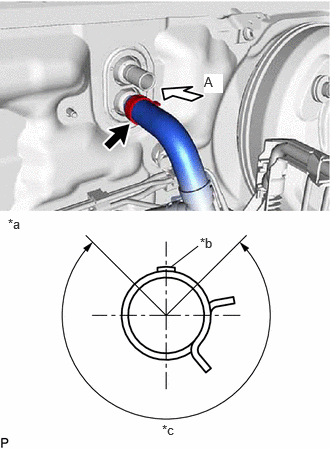
- CONNECT INLET HEATER WATER HOSE B
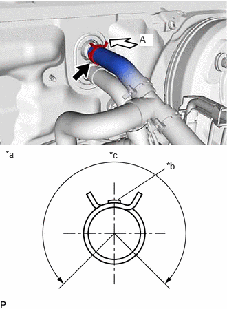
- CONNECT OUTLET HEATER WATER HOSE B (w/o Stop And Start System)
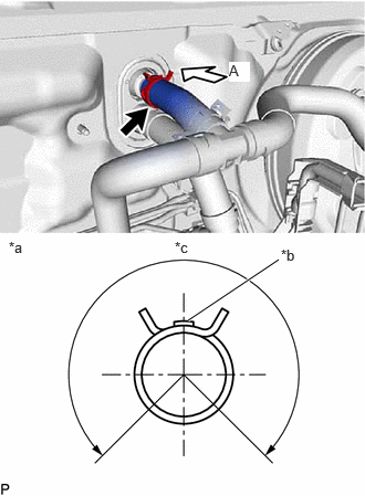
- CONNECT OUTLET HEATER WATER HOSE A (w/ Stop And Start System)
- CONNECT NO. 2 AIR CONDITIONER TUBE AND ACCESSORY ASSEMBLY
- Remove the vinyl tape from the No. 2 air conditioner tube and accessory assembly.
- Sufficiently apply compressor oil to 2 new O-rings and the fitting surface of the No. 2 air conditioner tube and accessory assembly.
Compressor Oil
ND-OIL 12 or equivalent
- Install the O-rings to the No. 2 air conditioner tube and accessory assembly.NOTE:
Keep the O-rings and O-ring fitting surfaces free from dirt and foreign matter.
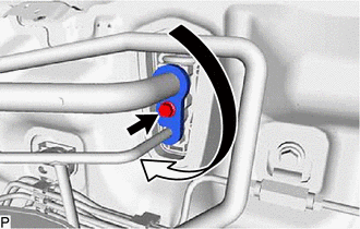
- Connect the No. 2 air conditioner tube and accessory assembly.
- Rotate the hook connector as shown in the illustration.
- Insert the tube joint into the fitting hole securely and install the bolt.
Torque: 9.8 N.m (100 kgf/cm, 87 in.lbf)
- INSTALL COWL VENTILATOR PANEL SUB-ASSEMBLY
Refer to PROCEDURE - Step 15
- INSTALL FRONT UPPER SUSPENSION TO COWL BRACE SUB-ASSEMBLY LH
Refer to PROCEDURE - Step 16
- INSTALL FRONT UPPER SUSPENSION TO COWL BRACE SUB-ASSEMBLY RH
HINT:
Perform the same procedure as for the LH side.
- INSTALL FRONT FENDER SPLASH SHIELD SEAL FRONT LH
Refer to PROCEDURE - Step 18
- INSTALL FRONT FENDER SPLASH SHIELD SEAL FRONT RH
HINT:
Perform the same procedure as for the LH side.
- INSTALL FENDER SPLASH SHIELD SUB-ASSEMBLY REAR LH
Refer to PROCEDURE - Step 20
- INSTALL FENDER SPLASH SHIELD SUB-ASSEMBLY REAR RH
HINT:
Perform the same procedure as for the LH side.
- INSTALL WINDSHIELD WIPER MOTOR AND LINK ASSEMBLY
Refer to INSTALLATION [12/2019 - ]
- ADD ENGINE COOLANT
Refer to PROCEDURE - Step 2
- INSPECT FOR COOLANT LEAK
Refer to PROCEDURE - Step 1
- CHARGE AIR CONDITIONING SYSTEM WITH REFRIGERANT
Refer to PROCEDURE - Step 2
- WARM UP ENGINE
Refer to PROCEDURE - Step 3
- INSPECT FOR REFRIGERANT LEAK
Refer to PROCEDURE - Step 5