DTC P0450-11: Evaporative Emission System Pressure Sensor/Switch Circuit Short to Ground; DTC P0450-15: Evaporative Emission System Pressure Sensor/Switch Circuit Short to Battery or Open; DTC P0450-2A: Evaporative Emission System Pressure Sensor/Switch Signal Stuck in Range; DTC P0450-2F: Evaporative Emission System Pressure Sensor/Switch Signal Erratic [12/2019 - 10/2022]: Procedure
- CONFIRM DTC AND EVAP PRESSURE
- Read the DTCs.
Powertrain > Engine > Trouble Codes
- Read the EVAP (Evaporative Emission) pressure displayed on the GTS.
Powertrain > Engine > Data List
Tester Display Vapor Pressure Pump Result
Display (DTC Output) Test Result Suspected Trouble Area Proceed to P0450-11 Less than 42.11 kPa (abs) [6.11 psi (abs)] - Wire harness or connector (canister pressure sensor - ECM)
- Canister pressure sensor
- Short in ECM circuit
A P0450-15 Higher than 123.761 kPa (abs) [17.95 psi (abs)] - Wire harness or connector (canister pressure sensor - ECM)
- Canister pressure sensor
- Open in ECM circuit
B P0450-2A
P0450-2F- Canister pressure sensor C
Result:
B
See step 5
Result:
C
GO TO EVAP SYSTEM. Refer to EVAP System [12/2019 - 10/2022]
Result:
A
See step 2
- Read the DTCs.
- CHECK HARNESS AND CONNECTOR (CANISTER PUMP MODULE - ECM)
- Disconnect the ECM connector.
- Measure the resistance according to the value(s) in the table below.
Result
Tester Connection Condition Specified Condition Suspected Trouble Area Proceed to A28-36 (PPMP) - Body ground Always Below 10 Ω - Wire harness or connector (canister pressure sensor - ECM)
- Short in canister pressure sensor circuit
A 10 kΩ or higher - Wire harness or connector (canister pressure sensor - ECM)
- Short in ECM circuit
B
Result:
B
See step 4
Result:
A
See step 3
- CHECK HARNESS AND CONNECTOR (CANISTER PUMP MODULE - ECM)
- Disconnect the canister pump module connector.
- Disconnect the ECM connector.
- Measure the resistance according to the value(s) in the table below.
Result
Tester Connection Condition Specified Condition Suspected Trouble Area Proceed to A28-36 (PPMP) - Body ground Always 10 kΩ or higher Short in canister pressure sensor circuit A Below 10 Ω Short in wire harness or connector (canister pressure sensor - ECM) B
Result:
A
See step 6
Result:
B
See step 7
- REPLACE ECM
Refer to REMOVAL [12/2019 - 09/2020] , or refer to REMOVAL [09/2020 - 10/2022]
Result
Proceed to NEXT Result:
NEXT
See step 8
- CHECK HARNESS AND CONNECTOR (CANISTER PUMP MODULE - ECM)
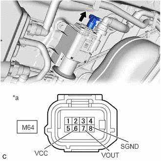
*a Front view of wire harness connector
(to Canister Pump Module)- Disconnect the canister pump module connector.
- Measure the resistance according to the value(s) in the table below.
Standard Resistance
Tester Connection Condition Specified Condition M64-8 (SGND) - Body ground Always 100 Ω or less - Turn the ignition switch to ON.
- Measure the voltage according to the value(s) in the table below.
Standard Voltage
Tester Connection Condition Specified Condition M64-6 (VCC) - Body ground Ignition switch ON 4.5 to 5.5 V M64-7 (VOUT) - Body ground Ignition switch ON 4.5 to 5.5 V Result
Test Result Suspected Trouble Area Proceed to Voltage and resistance within standard ranges Open in canister pressure sensor circuit A Voltage and/or resistance outside standard ranges Open in wire harness or connector (canister pressure sensor - ECM) B
Result:
B
See step 7
Result:
A
See step 6
- REPLACE CANISTER PUMP MODULE
Refer to REMOVAL [12/2019 - 10/2022]
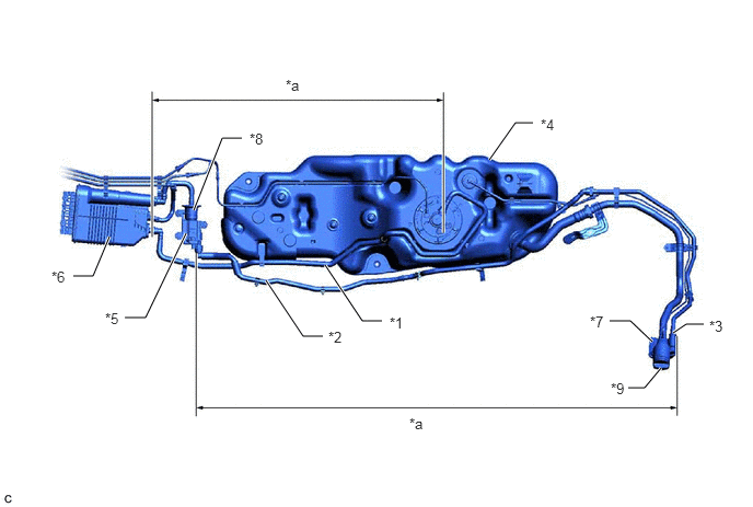
NOTE:- When replacing the canister pump module, check the canister pump module interior, canister interior and related pipes for water, fuel and other liquids. If liquids are present, check for disconnections and/or cracks in the following: 1) the pipe from the air inlet port to the canister pump module; 2) the canister filter; and 3) the fuel tank vent hose. If liquids are present in the canister interior, replace the canister and canister pump module together.
- Check for filter blockage in the canister. If the charcoal filter inside the canister is clogged, replace the canister and canister pump module together.
- Check for filter blockage in the canister filter. If the canister filter has blockages, replace the canister filter.
*1 Fuel Tank Vent Hose *2 Vent Hose *3 Air Inlet Port *4 Fuel Tank *5 Canister Pump Module *6 Canister *7 Canister Filter *8 No. 2 Charcoal Canister Filter *9 Fuel Tank Cap - - *a Inspection Area
(check for disconnection and/or cracks)- - Result
Proceed to NEXT Result:
NEXT
See step 8
- REPAIR OR REPLACE HARNESS OR CONNECTOR (CANISTER PUMP MODULE - ECM)
Result:
NEXT
See step 8
- CLEAR DTC
- Clear the DTCs.
Powertrain > Engine > Clear DTCs
- Turn the ignition switch off and wait for at least 30 seconds.
Result
Proceed to NEXT
Result:
NEXT
See step 9
- Clear the DTCs.
- CHECK WHETHER DTC OUTPUT RECURS (DTC P0450-11 OR P0450-15)
- Perform the Evaporative System Check using the GTS, referring to Confirmation Driving Pattern.
- Check the DTC judgment result.
Powertrain > Engine > Utility
Tester Display All Readiness GTS Display Description NORMAL - DTC judgment completed
- System normal
ABNORMAL - DTC judgment completed
- System abnormal
INCOMPLETE - DTC judgment not completed
- Perform driving pattern after confirming DTC enabling conditions
- Input the DTC: P0450-11 or P0450-15.
Result
Proceed to NEXT
Result:
NEXT
END