ACIS Control Circuit [12/2019 - 10/2022]: Procedure
- PERFORM ACTIVE TEST USING GTS (ACTIVATE THE VSV FOR INTAKE CONTROL)
- Start the engine.
- According to the display on the GTS, perform the Active Test to operate the No. 1 vacuum switching valve assembly (for intake air control valve sub-assembly) and check for the operating sound of the intake air control valve sub-assembly in the intake air surge tank assembly.
Powertrain > Engine > Active Test
Tester Display Activate the VSV for Intake Control OK
Operating sounds can be heard.
Result
Proceed to OK NG
Result:
OK
PROCEED TO NEXT SUSPECTED AREA SHOWN IN PROBLEM SYMPTOMS TABLE. Refer to PROBLEM SYMPTOMS TABLE [12/2019 - 10/2022]
Result:
NG
See step 2
- INSPECT INTAKE AIR SURGE TANK ASSEMBLY (INTAKE AIR CONTROL VALVE SUB-ASSEMBLY OPERATION)
Refer to ON-VEHICLE INSPECTION [12/2019 - 10/2022]
Result
Proceed to OK NG Result:
NG
REPLACE INTAKE AIR SURGE TANK ASSEMBLY. Refer to REMOVAL [12/2019 - 10/2022]
Result:
OK
See step 3
- INSPECT VACUUM HOSE SUB-ASSEMBLY (NO. 1 VACUUM SWITCHING VALVE ASSEMBLY (FOR INTAKE AIR CONTROL VALVE SUB-ASSEMBLY) - INTAKE AIR SURGE TANK ASSEMBLY)
- Check the vacuum hose sub-assembly (No. 1 vacuum switching valve assembly (for intake air control valve sub-assembly) - intake air surge tank assembly) for looseness, disconnection and blockage.
OK
No looseness, disconnection or blockage.
Result
Proceed to OK NG
Result:
NG
REPAIR OR REPLACE VACUUM HOSE SUB-ASSEMBLY
Result:
OK
See step 4
- Check the vacuum hose sub-assembly (No. 1 vacuum switching valve assembly (for intake air control valve sub-assembly) - intake air surge tank assembly) for looseness, disconnection and blockage.
- CHECK VACUUM
- Disconnect the vacuum hose sub-assembly from the No. 1 vacuum switching valve assembly (for intake air control valve sub-assembly).
- Start the engine.
- Using your finger, confirm that the hose has suction.
Result
Result Proceed to Suction applied A No suction B
Result:
B
See step 9
Result:
A
See step 5
- Disconnect the vacuum hose sub-assembly from the No. 1 vacuum switching valve assembly (for intake air control valve sub-assembly).
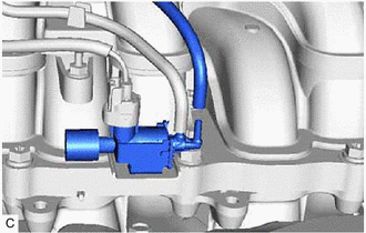
- INSPECT NO. 1 VACUUM SWITCHING VALVE ASSEMBLY (FOR INTAKE AIR CONTROL VALVE SUB-ASSEMBLY)
Refer to INSPECTION [12/2019 - 10/2022]
Result
Proceed to OK NG Result:
NG
REPLACE NO. 1 VACUUM SWITCHING VALVE ASSEMBLY (FOR INTAKE AIR CONTROL VALVE SUB-ASSEMBLY). Refer to REMOVAL [12/2019 - 10/2022]
Result:
OK
See step 6
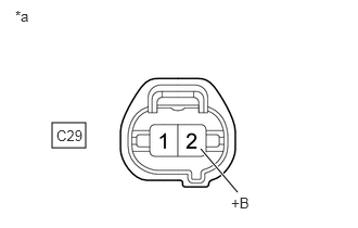
- CHECK TERMINAL VOLTAGE (POWER SOURCE OF NO. 1 VACUUM SWITCHING VALVE ASSEMBLY (FOR INTAKE AIR CONTROL VALVE SUB-ASSEMBLY))
- Disconnect the No. 1 vacuum switching valve assembly (for intake air control valve sub-assembly) connector.
*a Front view of wire harness connector
(to No. 1 Vacuum Switching Valve Assembly (for Intake Air Control Valve Sub-assembly)) - Turn the ignition switch to ON.
- Measure the voltage according to the value(s) in the table below.
Standard Voltage
Tester Connection Condition Specified Condition C29-2(+B) - Body ground Ignition switch ON 11 to 14 V Result
Proceed to OK NG
Result:
NG
See step 8
Result:
OK
See step 7
- Disconnect the No. 1 vacuum switching valve assembly (for intake air control valve sub-assembly) connector.
- CHECK HARNESS AND CONNECTOR (NO. 1 VACUUM SWITCHING VALVE ASSEMBLY (FOR INTAKE AIR CONTROL VALVE SUB-ASSEMBLY) - ECM)
- Disconnect the No. 1 vacuum switching valve assembly (for intake air control valve sub-assembly) connector.
- Disconnect the ECM connector.
- Measure the resistance according to the value(s) in the table below.
Standard Resistance
Tester Connection Condition Specified Condition C29-1 (ACIS) - C54-66 (ACIS) Always Below 1 Ω C29-1 (ACIS) or C54-66 (ACIS) - Body ground and other terminals Always 10 kΩ or higher Result
Proceed to OK NG
Result:
OK
REPLACE ECM. Refer to REMOVAL [12/2019 - 09/2020] , or refer to REMOVAL [09/2020 - 10/2022]
Result:
NG
REPAIR OR REPLACE HARNESS OR CONNECTOR
- CHECK HARNESS AND CONNECTOR (EFI-MAIN RELAY - NO. 1 VACUUM SWITCHING VALVE ASSEMBLY (FOR INTAKE AIR CONTROL VALVE SUB-ASSEMBLY))
- Remove the EFI-MAIN relay, FUEL PMP relay and A/F HTR relay from the No. 1 engine room relay block and No. 1 junction block assembly.
HINT:
Remove the FUEL PMP and A/F HTR relays connected between the checked terminals as the coil inside the relay influences the measurement value.
- Disconnect the No. 1 vacuum switching valve assembly (for intake air control valve sub-assembly) connector.
- Measure the resistance according to the value(s) in the table below.
Standard Resistance
Tester Connection Condition Specified Condition 5 (EFI-MAIN relay) - C29-2 (+B) Always Below 1 Ω 5 (EFI-MAIN relay) or C29-2 (+B) - Body ground and other terminals Always 10 kΩ or higher Result
Proceed to OK NG
Result:
OK
GO TO ECM POWER SOURCE CIRCUIT. Refer to ECM Power Source Circuit [12/2019 - 10/2022]
Result:
NG
REPAIR OR REPLACE HARNESS OR CONNECTOR
- Remove the EFI-MAIN relay, FUEL PMP relay and A/F HTR relay from the No. 1 engine room relay block and No. 1 junction block assembly.
- INSPECT VACUUM PUMP ASSEMBLY
Refer to ON-VEHICLE INSPECTION [12/2019 - 10/2022]
Result
Proceed to OK NG Result:
OK
REPAIR OR REPLACE VACUUM HOSE SUB-ASSEMBLY (NO. 1 VACUUM SWITCHING VALVE ASSEMBLY (FOR INTAKE AIR CONTROL VALVE SUB-ASSEMBLY) - VACUUM PUMP ASSEMBLY)
Result:
NG
REPLACE VACUUM PUMP ASSEMBLY. Refer to REMOVAL [12/2019 - 10/2022]