Ignition Circuit [12/2019 - 10/2022]: Procedure
- CHECK TERMINAL VOLTAGE (POWER SOURCE OF IGNITION COIL ASSEMBLY)
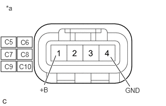
*a Front view of wire harness connector
(to Ignition Coil Assembly)- Disconnect the ignition coil assembly connectors.
- Turn the ignition switch to ON.
- Measure the voltage according to the value(s) in the table below.
Standard Voltage
Tester Connection Condition Specified Condition C5-1 (+B) - C5-4 (GND) Ignition switch ON 11 to 14 V C6-1 (+B) - C6-4 (GND) Ignition switch ON 11 to 14 V C7-1 (+B) - C7-4 (GND) Ignition switch ON 11 to 14 V C8-1 (+B) - C8-4 (GND) Ignition switch ON 11 to 14 V C9-1 (+B) - C9-4 (GND) Ignition switch ON 11 to 14 V C10-1 (+B) - C10-4 (GND) Ignition switch ON 11 to 14 V Result
Proceed to OK NG
Result:
NG
See step 3
Result:
OK
See step 2
- CHECK HARNESS AND CONNECTOR (IGNITION COIL ASSEMBLY - ECM)
- Disconnect the ignition coil assembly connectors.
- Disconnect the ECM connector.
- Measure the resistance according to the value(s) in the table below.
Standard Resistance
Tester Connection Condition Specified Condition C5-3 (IGT1) - C54-71 (IGT1) Always Below 1 Ω C6-3 (IGT2) - C54-36 (IGT2) Always Below 1 Ω C7-3 (IGT3) - C54-70 (IGT3) Always Below 1 Ω C8-3 (IGT4) - C54-35 (IGT4) Always Below 1 Ω C9-3 (IGT5) - C54-69 (IGT5) Always Below 1 Ω C10-3 (IGT6) - C54-34 (IGT6) Always Below 1 Ω C5-3 (IGT1) or C54-71 (IGT1) - Body ground and other terminals Always 10 kΩ or higher C6-3 (IGT2) or C54-36 (IGT2) - Body ground and other terminals Always 10 kΩ or higher C7-3 (IGT3) or C54-70 (IGT3) - Body ground and other terminals Always 10 kΩ or higher C8-3 (IGT4) or C54-35 (IGT4) - Body ground and other terminals Always 10 kΩ or higher C9-3 (IGT5) or C54-69 (IGT5) - Body ground and other terminals Always 10 kΩ or higher C10-3 (IGT6) or C54-34 (IGT6) - Body ground and other terminals Always 10 kΩ or higher Result
Proceed to OK NG
Result:
OK
REPLACE ECM. Refer to REMOVAL [12/2019 - 09/2020] , or refer to REMOVAL [09/2020 - 10/2022]
Result:
NG
REPAIR OR REPLACE HARNESS OR CONNECTOR
- CHECK HARNESS AND CONNECTOR (IGNITION COIL ASSEMBLY - BODY GROUND)
- Disconnect the ignition coil assembly connectors.
- Measure the resistance according to the value(s) in the table below.
Standard Resistance
Tester Connection Condition Specified Condition C5-4 (GND) - Body ground Always Below 1 Ω C6-4 (GND) - Body ground Always Below 1 Ω C7-4 (GND) - Body ground Always Below 1 Ω C8-4 (GND) - Body ground Always Below 1 Ω C9-4 (GND) - Body ground Always Below 1 Ω C10-4 (GND) - Body ground Always Below 1 Ω Result
Proceed to OK NG
Result:
NG
REPAIR OR REPLACE HARNESS OR CONNECTOR
Result:
OK
See step 4
- CHECK HARNESS AND CONNECTOR (IG2 NO. 1 RELAY - IGNITION COIL ASSEMBLY)
- Disconnect the IG2 NO. 1 relay from No. 1 engine room relay block and No. 1 junction block assembly.
- Disconnect the ignition coil assembly connectors.
- Measure the resistance according to the value(s) in the table below.
Standard Resistance
Tester Connection Condition Specified Condition 5 (IG2 NO. 1 relay) - C5-1 (+B) Always Below 1 Ω 5 (IG2 NO. 1 relay) - C6-1 (+B) Always Below 1 Ω 5 (IG2 NO. 1 relay) - C7-1 (+B) Always Below 1 Ω 5 (IG2 NO. 1 relay) - C8-1 (+B) Always Below 1 Ω 5 (IG2 NO. 1 relay) - C9-1 (+B) Always Below 1 Ω 5 (IG2 NO. 1 relay) - C10-1 (+B) Always Below 1 Ω 5 (IG2 NO. 1 relay) or C5-1 (+B) - Body ground and other terminals Always 10 kΩ or higher 5 (IG2 NO. 1 relay) or C6-1 (+B) - Body ground and other terminals Always 10 kΩ or higher 5 (IG2 NO. 1 relay) or C7-1 (+B) - Body ground and other terminals Always 10 kΩ or higher 5 (IG2 NO. 1 relay) or C8-1 (+B) - Body ground and other terminals Always 10 kΩ or higher 5 (IG2 NO. 1 relay) or C9-1 (+B) - Body ground and other terminals Always 10 kΩ or higher 5 (IG2 NO. 1 relay) or C10-1 (+B) - Body ground and other terminals Always 10 kΩ or higher Result
Proceed to OK NG
Result:
OK
GO TO ECM POWER SOURCE CIRCUIT. Refer to ECM Power Source Circuit [12/2019 - 10/2022]
Result:
NG
REPAIR OR REPLACE HARNESS OR CONNECTOR