Installation [12/2019 - 10/2022]: Procedure
- INSTALL FUEL SUCTION TUBE WITH PUMP AND GAUGE ASSEMBLY
- Install a new fuel suction tube set gasket to the fuel tank sub-assembly.
- Set the fuel suction tube with pump and gauge assembly to the fuel tank sub-assembly.NOTE:
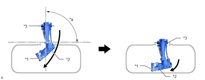
- Be careful not to bend the arm of the fuel sender gauge assembly.
- Make sure the horizontal angle of the fuel suction plate sub-assembly is less than 90°.
- To avoid applying excessive force to the tip of the fuel sender gauge assembly, tilt the fuel sub-tank sub-assembly diagonally and insert it into the fuel tank sub-assembly as shown in the illustration.
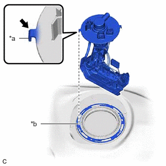
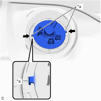
*1 Fuel Sender Gauge Assembly *2 Fuel Sub-tank Sub-assembly *3 Fuel Suction Plate Sub-assembly - - *a 90° - - *a Protrusion *b Notch - Align the protrusions of the fuel suction tube with pump and gauge assembly with the notches in the fuel tank sub-assembly.
*a Protrusion 
Notch
- INSTALL FUEL PUMP GAUGE RETAINER
- Install the fuel pump gauge retainer.
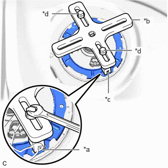
- While pressing down on the fuel suction tube with pump and gauge assembly, temporarily install the fuel pump gauge retainer.
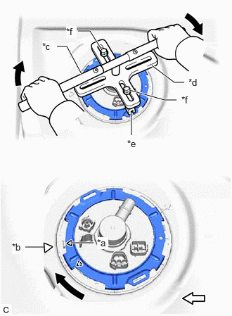
- Temporarily install SST (plate) and SST (claw) to the fuel pump gauge retainer.
- SST: 09808-01071
- SST: 09808-14031
- 09808-01030
- 09808-01090
*a Insertion Point *b SST (Plate) *c SST (Claw) *d SST (Bolt) HINT:
Securely insert the ends of SST (claw) into the insertion points in the fuel pump gauge retainer.
- While firmly pressing SST (claw) into the insertion points in the fuel pump gauge retainer, tighten SST (bolt).
- Install SST (handle) to SST (plate).
*a Triangle Mark (Fuel Pump Gauge Retainer) *b Triangle Mark (Fuel Tank Sub-assembly) *c SST (Handle) *d SST (Plate) *e SST (Claw) *f SST (Bolt) 
Front Side - SST: 09808-14031
- 09808-01010
- SST: 09808-14031
- Using SST, rotate the fuel pump gauge retainer so that the triangle mark on the fuel pump gauge retainer is aligned with the triangle mark on the fuel tank sub-assembly to install the fuel suction tube with pump and gauge assembly to the fuel tank sub-assembly.NOTE:
- Do not use any tools other than specified as this may result in damage to the fuel pump gauge retainer or fuel tank sub-assembly.
- Do not press down on SST excessively as this may make the fuel pump gauge retainer hard to rotate, and may damage components.
- Make sure to rotate SST (handle) horizontally. If it is rotated at an angle, SST may come off.
- Do not spin SST too fast or use an impact wrench as this may result in damage to components.
- If SST comes off of the fuel pump gauge retainer, loosen SST (bolt) and reinstall SST.
- Make sure that the fuel suction tube set gasket does not come off.
- Engage the claw to install the No. 1 fuel tube clamp.
- Install the fuel pump gauge retainer.
- CONNECT FUEL TANK MAIN TUBE SUB-ASSEMBLY
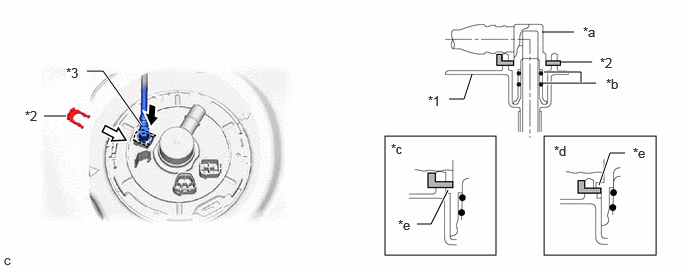
- Push the fuel tube joint onto the plug of the fuel suction plate sub-assembly, then install the tube joint clip.
*1 Fuel Suction Plate Sub-assembly *2 Tube Joint Clip *3 Fuel Tank Main Tube Sub-assembly - - *a Fuel Tube Joint *b O-ring *c Correct *d Incorrect *e Collar - - Insert Insert NOTE:- Check that there are no scratches or foreign matter around the connecting parts of the fuel tube joint and plug before performing this work.
- Check that the fuel tube joint is securely inserted to the end.
- Check that the tube joint clip is on the collar of the fuel tube joint.
- After installing the tube joint clip, check that the fuel tank main tube sub-assembly is securely connected by pulling on it.
- Push the fuel tube joint onto the plug of the fuel suction plate sub-assembly, then install the tube joint clip.
- CONNECT FUEL TANK EVAPORATION VENT TUBE SUB-ASSEMBLY
- Connect the fuel tank evaporation vent tube sub-assembly to the fuel suction tube with pump and gauge assembly.
Refer to PRECAUTION [12/2019 - 10/2022]
- Connect the fuel tank evaporation vent tube sub-assembly to the fuel suction tube with pump and gauge assembly.
- INSTALL REAR FLOOR SERVICE HOLE COVER
- Remove any remaining butyl tape from the rear floor service hole cover and vehicle body.
- Clean the installation surfaces of the rear floor service hole cover and vehicle body.
- Connect the 2 fuel suction tube with pump and gauge assembly connectors.
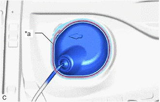
- Install the rear floor service hole cover with new butyl tape.
*a Butyl Tape Adhesion Area NOTE:Securely install the rear floor service hole cover.
- Return the rear floor silencer to its original position.
- Return the front floor carpet assembly to its original position.
- CONNECT CABLE TO NEGATIVE BATTERY TERMINAL
Refer to PROCEDURE - Step 2
- INSPECT FOR FUEL LEAK
Refer to PROCEDURE - Step 1
- INSTALL REAR NO. 1 SEAT ASSEMBLY LH
- for Captain Seat Type:
Refer to INSTALLATION [12/2019 - ]
- for 60/40 Split Seat Type LH Side:
Refer to INSTALLATION [12/2019 - ]
- for Captain Seat Type:
- PERFORM INITIALIZATION
- Perform "Inspection After Repair" after replacing the fuel pump.
Refer to INITIALIZATION [12/2019 - 10/2022]
- Perform "Inspection After Repair" after replacing the fuel pump.