Installation [12/2019 - 10/2022]: Procedure
- TEMPORARILY INSTALL FUEL (ENGINE ROOM SIDE) PUMP ASSEMBLY
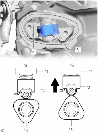
- Turn the crankshaft pulley until the flat of the camshaft faces the fuel pump lifter assembly.
*1 Fuel Pump Assembly *2 Fuel Pump Lifter Assembly *3 Camshaft *a Correct *b Incorrect *c Oil Collection Area HINT:
This prevents the camshaft nose from pushing up the fuel pump lifter assembly when installing the fuel pump assembly.
- Fill the fuel pump lifter housing oil collection areas with 30 cc (1.8 cu. in.) of engine oil from the fuel pump assembly hole of the cylinder head cover sub-assembly.
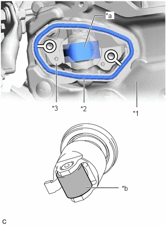
- Apply engine oil to the pump drive cam and fuel pump lifter assembly.
*1 Cylinder Head Cover Sub-assembly *2 Fuel Pump Spacer Gasket *3 Fuel Pump Lifter Housing *a Pump Drive Cam (Engine Oil Application Area) *b Fuel Pump Lifter Assembly (Engine Oil Application Area) - Install a new fuel pump spacer gasket to the cylinder head cover sub-assembly.
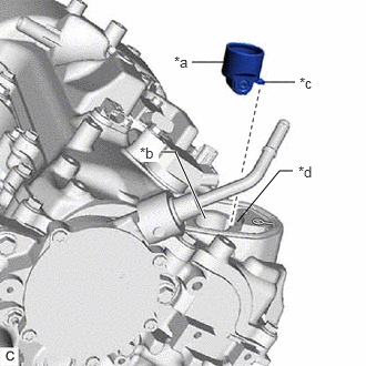
- Apply engine oil to the inside of the fuel pump lifter housing and the outside of the fuel pump lifter assembly.
*a Fuel Pump Lifter Assembly (Engine Oil Application Area) *b Fuel Pump Lifter Housing (Engine Oil Application Area) *c Stopper Key *d Key Groove - Set the fuel pump lifter assembly on the fuel pump lifter housing as shown in the illustration.
HINT:
Align the stopper key of the fuel pump lifter assembly with the key groove of the fuel pump lifter housing.
- Apply engine oil to a new O-ring and install it to the fuel pump assembly.NOTE:
Do not damage the O-ring.
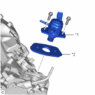
- Set the fuel pump lifter guide and fuel pump assembly on the cylinder head cover sub-assembly as shown in the illustration.
*1 Fuel Pump Assembly *2 Fuel Pump Lifter Guide - Temporarily install the fuel pump assembly with the 2 bolts, leaving some allowance for left and right movement.
- Turn the crankshaft pulley until the flat of the camshaft faces the fuel pump lifter assembly.
- TEMPORARILY INSTALL NO. 1 FUEL PIPE SUB-ASSEMBLY NOTE:
Do not damage the seals of the union nuts of the No. 1 fuel pipe sub-assembly.
- Temporarily install the No. 1 fuel pipe sub-assembly to the fuel delivery pipe RH and tighten the union nut by hand.
- Temporarily install the No. 1 fuel pipe sub-assembly to the fuel pump assembly and tighten the union nut by hand.
- INSTALL FUEL (ENGINE ROOM SIDE) PUMP ASSEMBLY
HINT:
Perform "Inspection After Repair" after replacing the fuel pump assembly.
Refer to INITIALIZATION [12/2019 - 10/2022]
- Tighten the 2 bolts.
Torque: 26 N.m (265 kgf/cm, 19 ft.lbf)
- Connect the fuel pump assembly connector.
- Tighten the 2 bolts.
- INSTALL NO. 1 FUEL PIPE SUB-ASSEMBLY
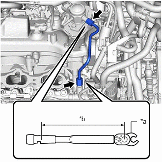
- Using a 17 mm union nut wrench, tighten the union nut on the fuel pump assembly side of the No. 1 fuel pipe sub-assembly.
*a 17 mm Union Nut Wrench *b Torque Wrench Fulcrum Length Specified tightening torque
Torque: 35 N.m (357 kgf/cm, 26 ft.lbf)
NOTE:Do not adjust the torque in the loosening direction.
HINT:
- Calculate the torque wrench reading when changing the fulcrum length of the torque wrench.
Refer to PRECAUTION [12/2019 - 11/2023]
- When using a 17 mm union nut wrench (fulcrum length of 30 mm (1.18 in.)) + torque wrench (fulcrum length of 180 mm (7.09 in.)): 30 N.m (306 kgf/cm, 22 ft.lbf)
- Calculate the torque wrench reading when changing the fulcrum length of the torque wrench.
- Using a 17 mm union nut wrench, tighten the union nut on the fuel delivery pipe RH side of the No. 1 fuel pipe sub-assembly.
Specified tightening torque
Torque: 35 N.m (357 kgf/cm, 26 ft.lbf)
NOTE:Do not adjust the torque in the loosening direction.
HINT:
- Calculate the torque wrench reading when changing the fulcrum length of the torque wrench.
Refer to PRECAUTION [12/2019 - 11/2023]
- When using a 17 mm union nut wrench (fulcrum length of 30 mm (1.18 in.)) + torque wrench (fulcrum length of 180 mm (7.09 in.)): 30 N.m (306 kgf/cm, 22 ft.lbf)
- Calculate the torque wrench reading when changing the fulcrum length of the torque wrench.
- Using a 17 mm union nut wrench, tighten the union nut on the fuel pump assembly side of the No. 1 fuel pipe sub-assembly.
- INSTALL FUEL HOSE BRACKET
- Install the fuel hose bracket to the cylinder head cover sub-assembly with the bolt.
Torque: 8.0 N.m (82 kgf/cm, 71 in.lbf)
- Install the fuel hose bracket to the cylinder head cover sub-assembly with the bolt.
- CONNECT NO. 2 FUEL TUBE SUB-ASSEMBLY
- Engage the clamp and connect the No. 2 fuel tube sub-assembly to the fuel pump assembly.
Refer to PRECAUTION [12/2019 - 10/2022]
- Engage the clamp and connect the No. 2 fuel tube sub-assembly to the fuel pump assembly.
- INSTALL FUEL PUMP PROTECTOR
- Install the fuel pump protector to the cylinder head sub-assembly with the 2 bolts.
Torque: 21 N.m (214 kgf/cm, 15 ft.lbf)
- Engage the clamp to connect the fuel tube sub-assembly to the fuel pump protector.
- Install the fuel pump protector to the cylinder head sub-assembly with the 2 bolts.
- INSTALL EXHAUST MANIFOLD ASSEMBLY RH (TWC: Front Catalyst) (for AWD)
Refer to INSTALLATION [12/2019 - 10/2022]
- INSTALL INTAKE MANIFOLD
Refer to INSTALLATION [12/2019 - 10/2022]
- CONNECT CABLE TO NEGATIVE BATTERY TERMINAL
Refer to PROCEDURE - Step 2
- INSPECT FOR FUEL LEAK
Refer to PROCEDURE - Step 1
- PERFORM INITIALIZATION
- Perform "Inspection After Repair" after replacing the fuel pump assembly.
Refer to INITIALIZATION [12/2019 - 10/2022]
- Perform "Inspection After Repair" after replacing the fuel pump assembly.