DTC P2530-14: Ignition Switch Circuit Short to Ground or Open [12/2019 - 10/2022]: Procedure
- READ VALUE USING GTS (IG SWITCH)
- According to the display on the GTS, read the Data List.
Powertrain > Stop and Start > Data List
Tester Display IG Switch Result
GTS Display Result Proceed to IG Switch ON A OFF B
Result:
A
USE SIMULATION METHOD TO CHECK. Refer to HOW TO PROCEED WITH TROUBLESHOOTING [12/2019 - ]
Result:
B
See step 2
- According to the display on the GTS, read the Data List.
- CHECK HARNESS AND CONNECTOR (ENGINE STOP AND START ECU - INSTRUMENT PANEL JUNCTION BLOCK ASSEMBLY (IG2-NO. 2 RELAY))
- Disconnect the engine stop and start ECU connector.
- Disconnect the instrument panel junction block assembly connector.
- Measure the resistance according to the value(s) in the table below.
Standard Resistance
Tester Connection Condition Specified Condition H66-18 (IG2) - 4B-32 Always Below 1 Ω H66-18 (IG2) or 4B-32 - Body ground and other terminals Always 10 kΩ or higher Result
Proceed to OK NG
Result:
NG
REPAIR OR REPLACE HARNESS OR CONNECTOR
Result:
OK
See step 3
- INSPECT INSTRUMENT PANEL JUNCTION BLOCK ASSEMBLY (IG2-NO. 2 RELAY)
- Remove the instrument panel junction block assembly.
- Measure the resistance according to the value(s) in the table below.
Standard Resistance
Tester Connection Condition Specified Condition 4E-1 - 4B-32 Battery positive (+) → 4A-17
Battery negative (-) → 4B-3Below 1 Ω 4E-1 - 4B-32 Battery not connected to 4A-17 and 4B-3 10 kΩ or higher Result
Proceed to OK NG
Result:
NG
REPLACE INSTRUMENT PANEL JUNCTION BLOCK ASSEMBLY (IG2-NO. 2 RELAY). Refer to REMOVAL [12/2019 - 10/2022]
Result:
OK
See step 4
- INSPECT INSTRUMENT PANEL JUNCTION BLOCK ASSEMBLY
- Remove the instrument panel junction block assembly.
- Measure the resistance according to the value(s) in the table below.
Standard Resistance
Tester Connection Condition Specified Condition 4A-17 - 4C-12 Always Below 1 Ω 4A-17 or 4C-12 - Body ground and other terminals Always 10 kΩ or higher Result
Proceed to OK NG
Result:
NG
REPLACE INSTRUMENT PANEL JUNCTION BLOCK ASSEMBLY. Refer to REMOVAL [12/2019 - 10/2022]
Result:
OK
See step 5
- CHECK HARNESS AND CONNECTOR (INSTRUMENT PANEL JUNCTION BLOCK ASSEMBLY (IG2-NO. 2 RELAY) - BODY GROUND)
- Disconnect the instrument panel junction block assembly connector.
- Measure the resistance according to the value(s) in the table below.
Standard Resistance
Tester Connection Condition Specified Condition 4B-3 - Body ground Always Below 1 Ω Result
Proceed to OK NG
Result:
NG
REPAIR OR REPLACE HARNESS OR CONNECTOR
Result:
OK
See step 6
- CHECK HARNESS AND CONNECTOR (INSTRUMENT PANEL JUNCTION BLOCK ASSEMBLY (IG2-NO. 2 RELAY) - CERTIFICATION ECU (SMART KEY ECU ASSEMBLY))
- Disconnect the instrument panel junction block assembly connector.
- Disconnect the certification ECU (smart key ECU assembly) connector.
- Measure the resistance according to the value(s) in the table below.
Standard Resistance
Tester Connection Condition Specified Condition 4A-17 - H48-17 (IG1D) Always Below 1 Ω 4A-17 or H48-17 (IG1D) - Body ground and other terminals Always 10 kΩ or higher Result
Proceed to OK NG
Result:
NG
REPAIR OR REPLACE HARNESS OR CONNECTOR
Result:
OK
See step 7
- CHECK HARNESS AND CONNECTOR (IG2 NO. 1 RELAY - CERTIFICATION ECU (SMART KEY ECU ASSEMBLY))
- Remove the IG2 NO. 1 relay from the No. 1 engine room relay block and No. 1 junction block assembly.
- Disconnect the certification ECU (smart key ECU assembly) connector.
- Disconnect the instrument panel junction block assembly 4B connector.
HINT:
Disconnect the IG1-NO. 1, IG1-NO. 2 and IG2-NO. 2 relays connected between the checked terminals as the coil inside the relay influences the measurement value.
- Measure the resistance according to the value(s) in the table below.
Standard Resistance
Tester Connection Condition Specified Condition 1 (IG2 NO. 1 relay) - H48-17 (IG1D) Always Below 1 Ω 1 (IG2 NO. 1 relay) or H48-17 (IG1D) - Body ground and other terminals Always 10 kΩ or higher Result
Proceed to OK NG
Result:
NG
REPAIR OR REPLACE HARNESS OR CONNECTOR
Result:
OK
See step 8
- CHECK HARNESS AND CONNECTOR (ENGINE STOP AND START ECU - EFI-MAIN RELAY)
- Disconnect the engine stop and start ECU connector.
- Remove the EFI-MAIN relay, FUEL PMP relay and A/F HTR relay from the No. 1 engine room relay block and No. 1 junction block assembly.
HINT:
Remove the FUEL PMP and A/F HTR relays connected between the checked terminals as the coil inside the relay influences the measurement value.
- Measure the resistance according to the value(s) in the table below.
Standard Resistance
Tester Connection Condition Specified Condition A34-1 (+B) - 5 (EFI-MAIN relay) Always Below 1 Ω A34-1 (+B) or 5 (EFI-MAIN relay) - Body ground and other terminals Always 10 kΩ or higher Result
Proceed to OK NG
Result:
NG
REPAIR OR REPLACE HARNESS OR CONNECTOR
Result:
OK
See step 9
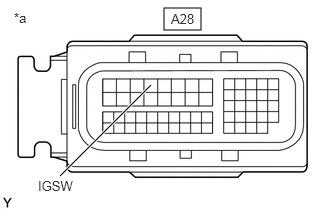
- CHECK ECM (IGSW TERMINAL VOLTAGE)
- Disconnect the ECM connector.
*a Front view of wire harness connector
(to ECM) - Turn the ignition switch to ON.
- Measure the voltage according to the value(s) in the table below.
Standard Voltage
Tester Connection Condition Specified Condition A28-4 (IGSW) - Body ground Ignition switch ON 11 to 14 V Result
Proceed to OK NG
Result:
NG
GO TO ECM POWER SOURCE CIRCUIT. Refer to ECM Power Source Circuit [12/2019 - 10/2022]
Result:
OK
See step 10
- Disconnect the ECM connector.
- INSPECT EFI-MAIN RELAY
Refer to ON-VEHICLE INSPECTION [12/2019 - 10/2022]
Result
Proceed to OK NG Result:
NG
REPLACE EFI-MAIN RELAY
Result:
OK
See step 11
- CHECK HARNESS AND CONNECTOR (EFI-MAIN NO. 1 RELAY - ECM)
HINT:
If communication between the GTS and vehicle is possible and SFI system data can be read 30 seconds after turning the ignition switch off a malfunction in the EFI-MAIN relay circuit is suspected.
- Remove the EFI-MAIN relay from the No. 1 engine room relay block and No. 1 junction block assembly.
- Disconnect the ECM connector.
- Measure the resistance according to the value(s) in the table below.
Standard Resistance
Tester Connection Condition Specified Condition 2 (EFI-MAIN relay) - A28-46 (MREL) Always Below 1 Ω 2 (EFI-MAIN relay) or A28-46 (MREL) - Body ground and other terminals Always 10 kΩ or higher Result
Proceed to OK NG
Result:
NG
REPAIR OR REPLACE HARNESS OR CONNECTOR
Result:
OK
See step 12
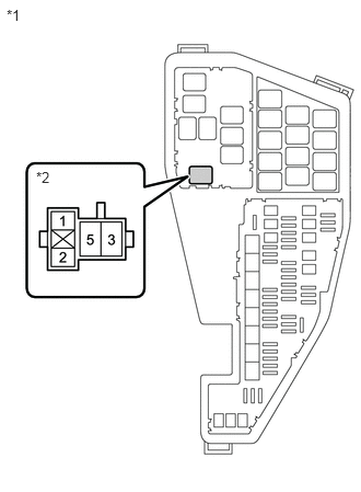
- CHECK TERMINAL VOLTAGE (POWER SOURCE OF EFI-MAIN RELAY)
*1 No. 1 Engine Room Relay Block and No. 1 Junction Block Assembly *2 EFI-MAIN Relay - Remove the EFI-MAIN relay from the No. 1 engine room relay block and No. 1 junction block assembly.
- Measure the voltage according to the value(s) in the table below.
Standard Voltage
Tester Connection Condition Specified Condition 3 (EFI-MAIN relay) - Body ground Always 11 to 14 V Result
Proceed to OK NG
Result:
NG
REPAIR OR REPLACE HARNESS OR CONNECTOR (BATTERY - EFI-MAIN RELAY)
Result:
OK
See step 13
- CHECK HARNESS AND CONNECTOR (EFI-MAIN RELAY - BODY GROUND)
- Remove the EFI-MAIN relay from the No. 1 engine room relay block and No. 1 junction block assembly.
- Measure the resistance according to the value(s) in the table below.
Standard Resistance
Tester Connection Condition Specified Condition 1 (EFI-MAIN relay) - Body ground Always Below 1 Ω Result
Proceed to OK NG
Result:
NG
REPAIR OR REPLACE HARNESS OR CONNECTOR
Result:
OK
See step 14
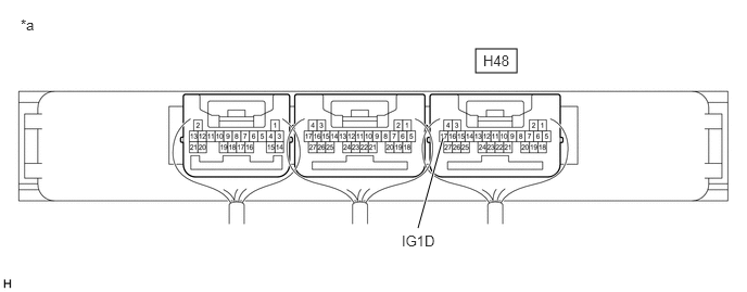
- CHECK CERTIFICATION ECU (SMART KEY ECU ASSEMBLY) (IG1D TERMINAL VOLTAGE)
*a Component with harness connected
(Certification ECU (Smart Key ECU Assembly))- - - Measure the voltage according to the value(s) in the table below.
Standard Voltage
Tester Connection Condition Specified Condition H48-17 (IG1D) - Body ground Ignition switch ACC Below 1 V Ignition switch ON 9 V or higher Result
Proceed to OK NG
Result:
OK
REPLACE ENGINE STOP AND START ECU. Refer to REMOVAL [12/2019 - 10/2022]
Result:
NG
REPLACE CERTIFICATION ECU (SMART KEY ECU ASSEMBLY). Refer to REMOVAL [12/2019 - 11/2023]
- Measure the voltage according to the value(s) in the table below.